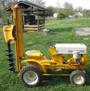
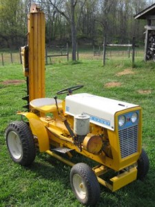
I had been looking for a CD-1 and collecting literature about them for about 20 years. I had exchanged emails with a gentleman (first name Jim) in May of 2011 concerning a CD-1 posthole digger that he’d recently purchased. In one of the emails I told him I’d be interested in purchasing it if he ever decided to sell. In March of 2012 Jim contacted me and said he was considering selling the CD-1 if I was still interested. Of course I was, and we soon struck a deal.
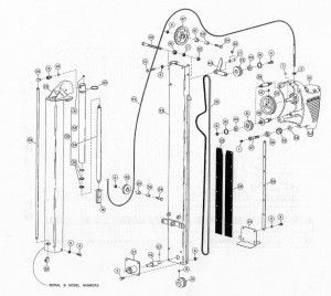
The CD-1 posthole digger I purchased (Serial No. 1116, Manufactured March, 1968) from Jim was originally mounted on a Bolens. The digger assembly shown below of the CD-1 is the same for all garden tractors. Everything shown in the parts breakdown below is the same (even for the Allis A-10). The diggers differ only in the mounting and drive for each specific make of garden tractor. It may not be obvious in the picture, but in operation the digger auger head is raised and lowered by a cable attached to a hydraulic cylinder. The auger rotation is produced by a dual v-belt drive powered by the garden tractor PTO through a jack shaft on the digger.
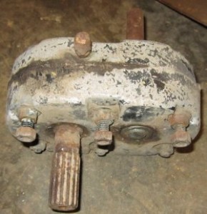
There are several differences in the mounting for a Bolens and a Cub Cadet. The undercarriage for a Bolens is much shorter than for a Cub cadet and attaches differently, the Bolens PTO output rotates in the wrong direction for the digger input, the hydraulic pump rotates in the opposite direction and the digger is mounted on the right rear for a Bolens rather than the left rear as for a Cub Cadet. Consequently, one of the things the Bolens required was a gearbox to reverse the direction of rotation.
The gearbox is not required for a Cub Cadet.
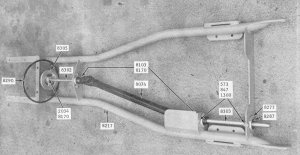
Jim had used the rear section of the shorter Bolens undercarriage to make an undercarriage for a Cub Cadet. He had also moved the digger mounting from the right rear to the left rear. The sketch of the required Cub Cadet frame is shown in the picture below.
Jim had made a good start on converting the Bolens frame to a Cub Cadet frame.

When I purchased the digger I mounted it on a Model 71 Cub Cadet to “check out” the fit and determine how much more work would be required.
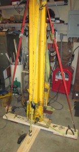
When I received the digger, the auger head was at its top position. I had to lift the auger head to mount the digger on the tractor. And, boy was it heavy!!! So the first thing was to figure out an easier method of removing and mounting the digger on the tractor. I attempted removing the digger with the auger head in its lowest position hoping it would stand upright on its own. But it wouldn’t do that. After a lot of looking and thinking, I figured out a stand to hold the digger when it was removed from the tractor. It consisted of two 4 foot long sections of 2 by 6 connected in the form of an X with an eyebolt attached at the end of each section. I used tie down straps between the digger and eyebolts to hold the digger in the upright position. By placing supports under the center of the digger and the auger head, it was a simple matter to tilt the digger enough to take tension off the mounting bolts for mounting or dismounting.
There were several things that needed to be done to the subframe. Two shafts as well as a PTO shaft had to be installed to get power from the front PTO of the Cub Cadet to the rear of the frame to power the digger.
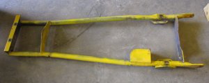
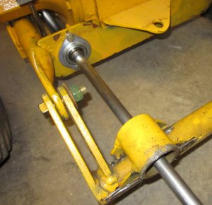
Danuser used 2 hole, stamped steel flange bearings to mount the two shafts. The flanges required a 2 1/8” clearance hole for each of the four bearings. While the frame was still on the tractor I marked the locations of the bearing centers and then removed the frame and drilled ¼” holes at the four locations.
I wasn’t sure how to make the 2 1/8” holes, but a good friend told me it could be done with a hole saw. I drilled the first hole with a 2 ¼” hole saw to give myself an eighth inch of clearance. But I discovered the 2 ¼” hole saw resulted in a 2 3/8” diameter hole. While I could live with that, I really wanted a smaller hole so I used a 2 1/8” hole saw for the remaining 3 holes. The 2 ¼” hole that it produced was what I wanted. It wasn’t easy, but I got the four holes drilled.
In the picture it looks like the front hole might not be drilled, but it is drilled and has the bearing mounted.
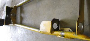
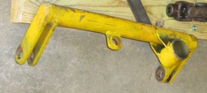
I had previously discovered that when the digger was moved from the right rear to the left rear the mount was welded back in the wrong position.
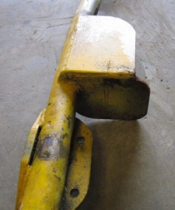
The large hollow cylinder on the mounting bracket shown above slides over the jackshaft on the digger assembly to mount the digger on the tractor.
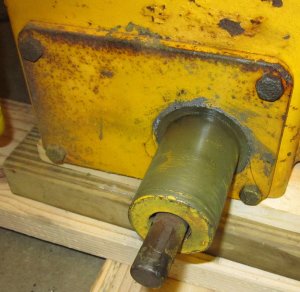
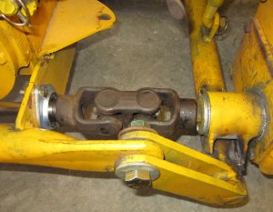
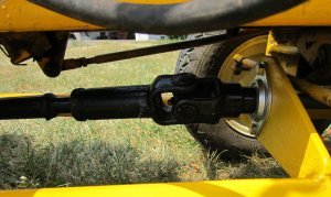
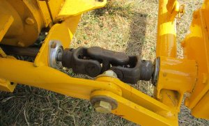
Power from the Cub Cadet is supplied to the digger through a yoke that connects to the jackshaft.
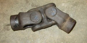
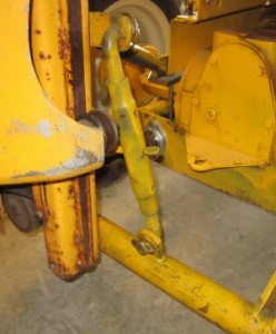
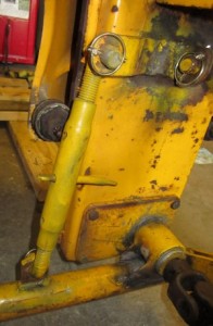
The double universal joints on the yoke allow for limited movement of the digger so that the user can drill a vertical hole on uneven ground. There are two adjustable links that allow for this vertical adjustment. One of the adjustable links allow for side tilt adjustment of the digger. Since this adjustment pivots the digger about the jackshaft there’s no problem with yoke alignment.
The other adjustable link allows for forward and backward tilt of the digger.
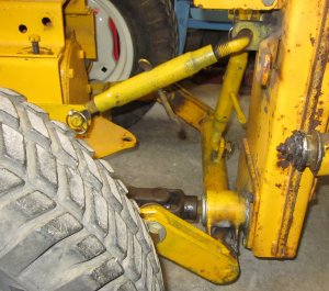
As can be seen in the above picture, this adjustment causes the mounting bracket to pivot about its two mounting points. Consequently, this adjustment changes the angle of the yoke which, as stated previously, only allows limited movement. To allow for the maximum possible forward and backward tilt, with the tractor on a horizontal surface and the digger in a perfectly vertical position, the yoke should be in a direct line with the drive shaft extending back from the Cub Cadet. When I purchased the digger, the yoke alignment was about an inch and a half too high with the digger in a perfectly vertical position. Unfortunately, I didn’t take a picture of that situation.
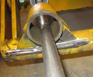
To correct the problem I cut the mounting loose from the support using an angle grinder with a cutoff wheel. I installed the two rear flange bearings and extended a three quarter inch shaft through the mount and the two bearings.
With the mounting in the correct position, I welded it in place. The new location allows for the maximum tilt in each direction.
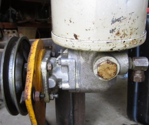
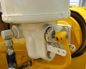
When I got the digger, Jim said he didn’t know how his neighbor had done it, but he’d reversed the direction of rotation of the hydraulic pump.
From the schematic of the pump it looks to me as though the thing that would be required to reverse the direction of operation for the pump would be to rotate the plate assembly (No. 17 in the schematic) 180 degrees. That would allow the input shaft to the pump to be on top thus reversing the direction of rotation of the pump. It appears that everything is symmetrical and it wouldn’t be a difficult thing to do. But I don’t plan to disassemble the pump to check it out.
Now the only things remaining were to add the supports for the front weight box, manufacture a weight box, and make the U-joint assembly that extends frim the front shaft to the rear shaft.
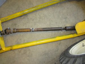
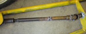
Jim provided me with a universal shaft that I could use for the connection. The shaft was too long and fit a shaft bigger than the three quarter inch shafts used on the CD-1, but it was easy to switch out the ends to match the 3/4 inch shafts. After that it was just a matter of cutting a section out of the shaft and welding the pieces back together.
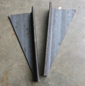
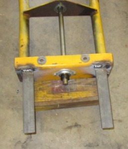
It was a pretty simple matter to make supports to mount the front weight bucket. I used the angle grinder with a cutoff wheel to make two supports and welded them to the front of the CD-1 frame.
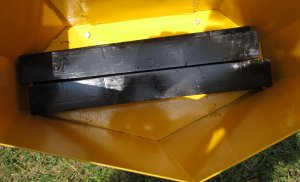
I used 16 gage sheet metal to make the weight bucket. The weight bucket is 16 inches high, 22 inches wide and 10 ½ inches deep.
Danuser used a weight bucket that was 12 inches deep, but a buddy supplied me with four 26 pound lead bars that fit nicely in the 10 ½ inch deep bucket.
I didn’t have the keyed shafting that I needed to complete the drive system, and I wanted to attend a local show, so I just used ¾” shafting with no keyways to temporarily complete the drive system for the show. After the show, I replaced the ¾” shaft with keyed shafting. I purchased a 5 inch diameter pulley for the front connection between the digger drive shaft and tractor PTO.
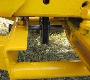
After connecting the driveshaft at the front and rear, the digger was ready to try out.
Right away I found a problem. The hydraulic valve that raises and lowers the auger head would “hang” every time the auger was raised to its upper limit. The only way that I could get the valve to release was to smack the end of the valve control with a rubber mallet.
I took the valve apart and cleaned and checked all the components. When I put the valve back together it no longer stuck when the auger head reached the upper limit, but it wouldn’t hold. It let the auger head creep back down. Rather than try anything further with the valve, I purchased and installed a flow control valve. The flow control valve allows for free flow to the cylinder to raise the auger head and an adjustable flow to lower it. By turning the flow control knob to zero the auger head can be raised but will not lower until the knob is adjusted.
For just moving the digger around, I set the flow control to zero. To dig a hole, I open the flow control valve that lets the digger operate normally.
Pictures of the finished digger can be found here:
https://cubcadetman.com/cc/sde-attachments/danuser-cd-1/pictures/2014/02/pictures-of-my-cd-1/
A video of the digger in operation can be found in the Video section of this website.
I hope you enjoyed this article.
As always, if you have any questions or comments please contact me through this website.
