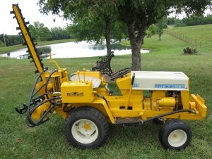
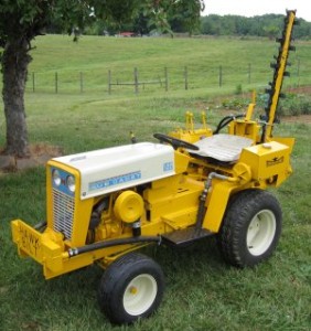
This is a copy of an article that was published in Lawn & Garden Tractor Magazine during 2013. It’s a great magazine, and I highly recommend it to you.
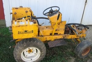
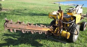
In early October, 2011, I saw an advertisement for a Hawk Bilt GroundSaw (Trencher). I searched the web, but could only find a few pictures and postings of brochures. There was very little discussion, no directions, no manuals, etc. I contacted the gentleman selling the GroundSaw and asked what he knew about it. He said that he had purchased it hoping to fix it up, but it was just in too bad of shape for him to mess with. He sent me lots of pictures, and we had several phone conversations. He was asking more than I really wanted to pay, but I just couldn’t resist the challenge of seeing if I could restore it and get it going. I have a lot of uses for a trencher, and it would make a very unique item to display. We agreed to meet at the Portland, Indiana Swap Meet in October where I could pick it up.
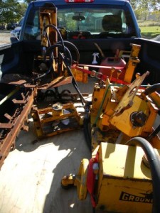
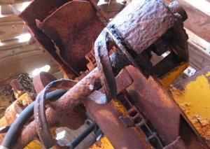
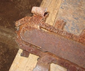
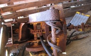
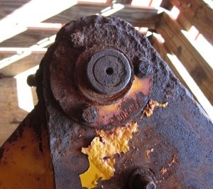
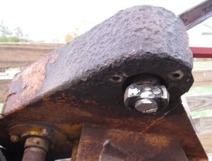
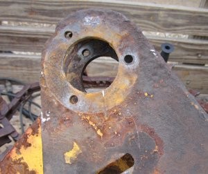
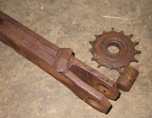
I was pleasantly surprised when I first saw the GroundSaw. Yes, it was in bad shape but not as bad as I had expected. The seller had sent me pictures of the worst parts of the saw. It was going to be a real challenge to get it going, but I was excited at the prospect. There were several missing pieces. The height adjuster, the connection between the front hydraulic pump and engine and the rear PTO sprocket were not there. I’ll discuss these as I discuss replacements. In addition, the dirt auger, the chain, the drive sprocket, bearings, shaft and auger itself were rusted beyond repair. About 21 inches of the chain that does the digging, as well as the “nose” sprocket and bearing were also too far gone to repair.
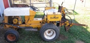
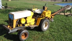
The saw was in two major pieces when I picked it up. One of the things I’ve learned while working on projects like this is that you should make them as mobile as possible. So, when I got it home, I unloaded the front section of the saw and sat it on a Cub Cadet Model 122 roller.
This section of the digger required two of the missing pieces–the drive section between the engine and hydraulic pump and the rear PTO driven sprocket.
I placed the rear section of the saw on a small trailer so I could easily move it in and out
of my shop.
The rear section required one of the missing pieces, the height adjuster. In addition it also required replacement of the dirt auger, the auger support bearings and shaft, the nose idler sprocket and a 21” section of the saw chain.
I began the process by disassembling all the parts that needed replacement. I started with the dirt auger. It wasn’t just a matter of removing bolts and sliding stuff apart. Everything was so rusted that parts had to be cut out.
A cutoff wheel on a small angle grinder is a must for this situation.
Two cutoff wheels and one Sawzall blade later, the shaft, bearings and dirt auger were all removed.
Although this section looked pretty bad at first glance, it was structurally sound. And the mountings for the two bearing flanges were in really good shape.
The next task was removing the chain and nose sprocket. Surprisingly, by starting where the chain was rusted in two, the chain came right off. Although the rollers were sometimes stiff, they easily freed up enough to be worked around the drive sprocket.
Two bolts held the end section that contained the nose sprocket in place. There was a one inch shaft through the center of the nose sprocket that was held in place by a roll pin. I bent both a standard punch and a roll pin punch but the roll pin wouldn’t budge. So I placed the whole assembly in a 20 ton press. I was pulling on the handle with both hands when there was a loud pop that sounded like a combination of the snap of a 22 rifle and the boom of a 12 gage shotgun. The shaft had moved about an eighth of an inch!!! Several pops later the shaft was out. The roll pin pieces were easy to drive out once the center shaft had been removed.
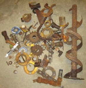
I was through disassembling and ready to start rebuilding! I had a large pile of scrap pieces including my Sawzall blade and the cutoff wheels.
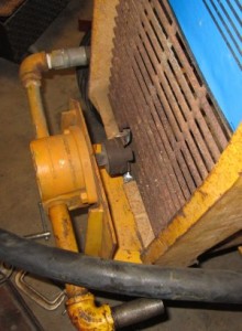
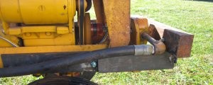
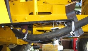
The hydraulic pump that connects to the front of the tractor and drives everything was still connected by hoses to the section I’d placed on the Cub Cadet. The hoses had already been kinked in the moving process so I decided to mount the pump to prevent any further damage. A section of the hose already needed replacing. The front pump has a mounting that attaches below the frame of the tractor and uses the same four bolts that hold the front grill housing in place. There had to be a section of the grill and grill housing cut out to allow a connection between the pump and tractor engine. I placed the grill housing in position on top of the pump support and marked the area that had to be removed. I started cutting it out with the Sawzall. About a quarter of the way around the cut it became obvious I wasn’t going to be able to cut the arc as small as I wanted. So, I drilled several small holes, took a big hammer and smacked the section really hard. Guess I was lucky but only the section I wanted to remove broke out. I used an angle grinder to smooth the entire section and produce the finished arc.
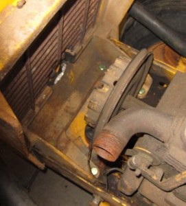
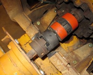
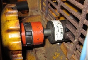
With the cut in the grill housing it was an easy matter to slide the grill into place and mark where it had to be cut. I used the cutoff wheel and dressed up the cuts with the angle grinder. Notice the space between the Love Joy coupling and the engine crankshaft. The coupling and shaft that belong there were missing in the original purchase. I already had several Love Joy couplings on hand that I could use to make the connection. However, I didn’t want to make this connection until all the hydraulic connections had been completed. In the picture below the Love Joy couplings are just lying in place. There is no shaft connecting them.
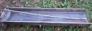
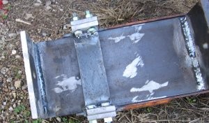
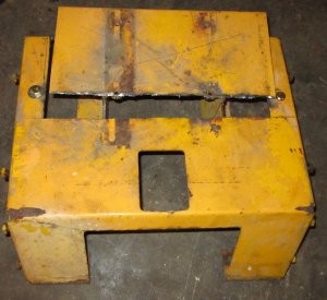
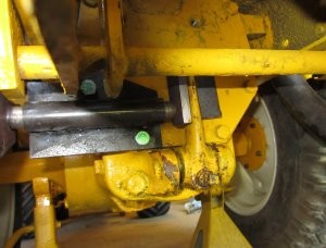
With the hydraulic pump mounted in front, I turned my attention to the missing height adjuster. The entire rear section of the saw is attached to a 6 ½ inch channel. Inside this channel there was supposed to be another channel that connected the rear section to the front section and allowed for height adjustment. The gentleman that sold the saw to me knew a guy that owned a Model 1200 Hawk Bilt GroundSaw and got the dimensions for me. It required a 28 inch long 6 inch channel. The 6 inch channel had to fit flush inside the 6 ½ inch channel. When I sat a standard 6 inch channel inside the 6 ½ inch channel, it stuck up above the sides of the 6 ½ inch channel. I marked the amount that needed to be removed, got out my trusty cutoff wheel and carefully cut the sides down to the correct height.
The picture above was taken later in the process after I’d already welded on an end cap, but you can see the piece that had to be removed from each side. I touched up the sides with an angle grinder after I finished the cut.
The discussion that follows will be easier to understand if I show what the finished completed assembly is supposed to look like.
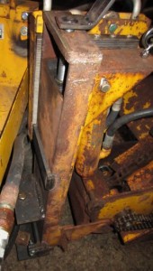
The inside 6 inch channel had to have two plates welded to it that would be connected to the front section of the saw. The top of the 6 inch channel had to have a ¾ inch screw that extended up through a plate welded on top of the outer 6 ½ inch channel. This screw had to have a handle on it that could be used to raise and lower the saw.
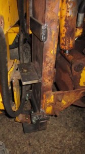
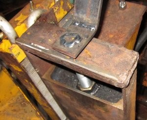
After the two plates were welded on the 6 inch channel, it had to be held in place inside the 6 ½ inch channel. In the original design the 6 inch channel was held in place inside the 6 ½ inch channel by two plates welded across the open face of the larger channel. I welded the upper plate across the open face of the channel as shown in a previous picture. But if I welded the bottom plate in position, it would be impossible to remove the inner channel without cutting these plates off. I don’t know why I would want to do that, but since the inside channel was missing, someone in the past obviously had a reason for removing it. I could barely make out where the original plates had been welded in place. I made a support that was mounted with 4 bolts to hold the bottom plate in position rather than welding. That way I could always remove the inner channel if I found a need.
The only thing left to do was attach a ¾ inch threaded rod to the top of the channel. I welded a ½ inch thick plate across the inside of the 6 inch channel, drilled a ¾ inch hole through it, welded a ¾ inch nut to the top side and screwed in the threaded rod. Fabricating and welding a handle to the top of the threaded rod completed the process.
With the height adjuster completed, the two halves of the saw could be connected and the entire saw was mobile.
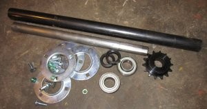
While I was working on the saw, I had ordered or purchased locally several items that would be required to rebuild the saw. For the dirt auger, I needed a 1 inch shaft with a key slot on one end, two bearings, four flanges, a sprocket and a 1 inch I.D. piece of tubing.
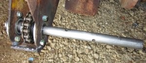
I drilled three 5/16 inch holes through the drive shaft and tube and mounted the shaft and bearings.
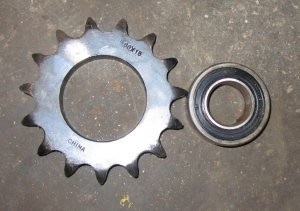
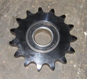
The “nose” sprocket on the outer end of the saw was a 15 tooth sprocket with a 1 inch bore for a number 2060 chain. I tried online, as well as at several local farm implement dealers, to find a replacement but was unsuccessful. I did manage to find a 15 tooth sprocket with a 2 inch bore and a ball bearing with a 2 inch O.D. and a 1 inch bore. I used Locktite to connect the two pieces together to “manufacture” my own idler sprocket.
I needed to replace 21 inches of 2060 chain so I purchased a 2 foot section.
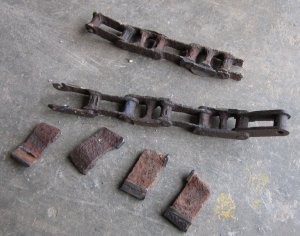
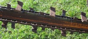
Obviously this section of chain needed to have teeth welded to it. To me, a lot of the challenge of a project like this is to keep the cost as reasonable as possible. Since the teeth on the rusted section of chain were still in fair to good condition, I used the cutoff wheel to remove these teeth and then welded them to the new section of chain. Unfortunately, I only took a picture of the smaller teeth I’d removed. I’d already welded the larger teeth on the replacement chain before I remembered to take a picture. You can see in the picture that the section of chain I was replacing was in bad shape.
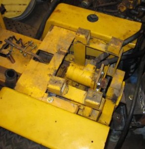
At this point, I could see “the light at the end of the tunnel”, so I ordered the hydraulic fittings I was going to need to finish the project. While I was waiting on this order, I decided to work on mounting the tractor fenders. On two pictures I’d found of a Model 1200 on the web, each fender just consisted of a small section of sheet metal behind the foot rest. I had been studying this since I first placed the front section of the saw on my Cub Cadet. Originally I had decided to mount two pieces of iron flat along each side of the rear section of the saw and bolt the fenders to it. But on further inspection it looked like I could use the Cub Cadet 122 seat support assembly if I cut out a section to clear the saw frame. Again, with the cutoff wheel and Sawzall, I cut out the required section.
With the section cut out, I slid the modified seat support into position around the saw frame. I had to weld two small angle sections to the saw frame for the seat support to be bolted to, but everything fit. The left fender easily slid into place, but the right fender had to have a hole cut out to clear part of the hydraulic controls. I liked the look of the finished result.
One of the things missing in my original purchase was the sprocket that mounted on the rear PTO. In operation, this sprocket is driven by a hydraulic motor which allows the user to control the ground speed of the saw by powering the tractor transmission through the rear PTO. Since it’s impossible to purchase a sprocket to fit the rear PTO of a Cub Cadet, I had to make my own. I already had a splined sleeve which fit the rear PTO that I’d purchased as an extra on another project. The sleeve had a 1.378” O.D. I purchased a weldable sprocket hub with a 1.375” I.D. and pressed the two together. Welding a 32 tooth, No. 50 chain sprocket to the hub finished the sprocket that I needed. Rather than try to line everything up and drill a hole to retain the sprocket in position on the rear PTO, I drilled and tapped the PTO shaft for a 5/16 – 18 bolt. A 5/16” bolt and washer hold the sprocket on the rear PTO.
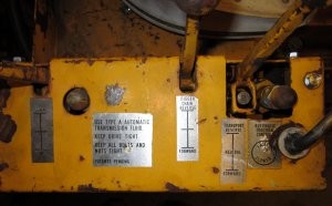
There was one other part that needed replacement before I finished the front hydraulic connection and tried out the GroundSaw. The GroundSaw has a “traction” control that is used to adjust the ground speed of the tractor during the digging operation.
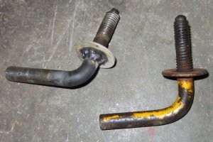
The threads on the control lever for the traction control were worn (or maybe weathered) to the point that it could only be used to make a minor adjustment. I cut extra threads on a 3/8 inch bolt, bent a handle and cut off the head of the bolt.
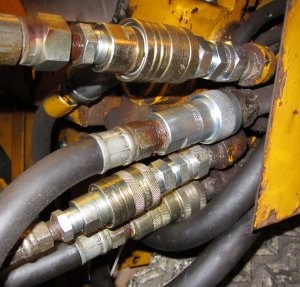
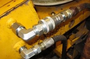
When the new hydraulic fittings and lines arrived, I completed the necessary hydraulic connections. I think the original design had all these connections as “permanent” connections. But on the GroundSaw I’d purchased, someone had used “snap couplers” for all the rear connections. With the snap couplers the complete rear section of the saw could be disconnected from the Cub Cadet without breaking into any hydraulic line. This seemed like a good idea to me, so when I replaced all these connections I used snap couplers. It would surely make painting easier. The couplers that came with the saw when I purchased it had been left lying on the ground so they had to be replaced.
With everything at least temporarily fixed, I could complete the connection for the front hydraulic drive and try out the GroundSaw.
When I started the engine and tried everything out, it all worked!!! However, there were a couple problems. First, the Cub Cadet was very light on the front end. Every time I would start moving, the front of the tractor would lift just a little bit. It didn’t help that you can’t slowly engage a hydraulic valve; it’s either engaged or disengaged. I needed additional weight on the front of the tractor. The other problem was that there was a wobble in the hydraulic motor that drives the digging chain. Upon inspection, I guessed there was probably a slight bend in the 1 inch shaft that supports this motor. Since the “wobble” wasn’t too bad and everything worked ok, I decided I’d put that off and think about it. I was more concerned about the light front end.
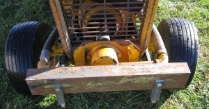
All the literature that I’d been able to locate for the Model 1200 showed it with a front blade mounted on the Cub Cadet. While that would add the weight that I needed, it also made the whole system a lot longer and more difficult to transport. I decided instead of using a front blade, I’d make a weight bracket and add weight. I found a piece of 2” by 4” steel that was 21” long and added it to the front of the tractor. This piece also acted as a front bumper to protect the hydraulic pump.
With the added front weight, everything worked as it should. We’d had too much rain to properly try out the GroundSaw, but I was confident everything would work.
I still had a few things to finish, but with a little paint, I felt it was going to look and work as it should. I needed to add the oil cooler, finish the dirt auger and decide if I wanted to do anything about the wobble in the main drive shaft.
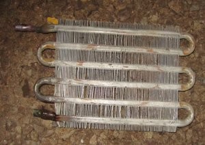
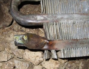
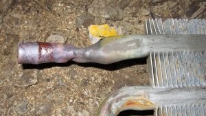
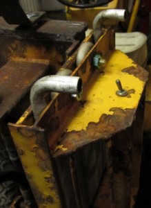
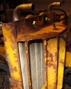
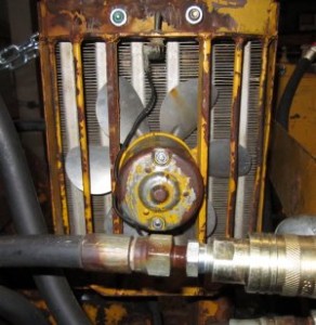
Since the oil cooler was in really rough shape, I had been putting off working on it. The inlet and outlet ports had been pretty badly beaten up and a lot of the fins were bent out of shape. I had just bypassed it earlier when I connected the hydraulics.
But, it’s better to be lucky than good. I’d been given a hood and a front grill from a Case 155 several years earlier. I’d about forgotten about it, but when I checked, the oil cooler on the Case was identical to the one on the GroundSaw. It was a simple matter to remove it from the Case’s front grill housing and bolt it into the GroundSaw’s support bracket. Since I would have to disassemble everything to do the painting, I decided to wait to make the hydraulic connections to the cooler after the painting was finished.
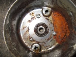
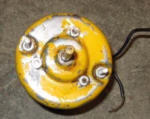
The fan motor for the cooling coil was another matter. It had sat out in the weather for so long that it was impossible to turn the armature. The armature shaft was so tight in the front bearing that the whole armature came out with that half of the motor. The top bearing was held in place by a system of spring fingers held in place by a cover plate which was held by three rivets. I had to drill the rivets out to remove the bearing and armature together. With the bearing and armature separated from the front cover I was able to remove the bearing. Since I didn’t have any rivets small enough to replace the three rivets I’d removed, I replaced them with three number 8 screws.
It wasn’t easy but I managed to get the springs and brushes back in place, the armature back in the motor and the front cover back on the motor. The motor was originally mounted on the GroundSaw with the two long bolts that hold the two halves of the motor together. The motor was supposed to fit flush against its mounting, but the three nuts on the number 8 screws I’d added meant the motor was no longer flush and the mounting screws were too short.
I replaced the two long bolts with two lengths of all thread that extended out from the motor far enough to remount the motor.
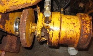
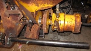
Since it was too cold to do any painting, it was a good time to look at the “wobble” in the chain drive motor. I had always assumed there was a coupling inside the end of the motor housing that connected the motor to a long shaft that drove the chain and dirt auger. Upon closer inspection I realized that the flywheel served as the coupling between the hydraulic motor and the main shaft.
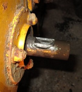
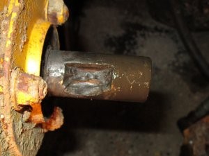
There were two setscrews in the flywheel coupler on the side of the hydraulic motor and two on the side of the main shaft. The motor shaft extended into the flywheel coupler about 2 inches and contained a half-moon key. All of that looked in good condition. The main shaft on the other end also extended into the flywheel coupler about 2 inches and contained a half-moon key. That connection didn’t look so good.
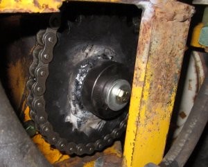
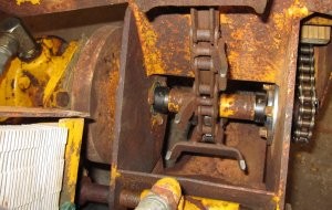
The picture on the left is the shaft just when I removed the flywheel coupler. The picture on the right is the shaft after the piece of metal fell out. I should also mention that only one of the setscrews on each end was tight when I removed the flywheel coupler. Since the shaft was ruined beyond repair, it made the removal process a lot easier. I used the Sawzall to cut the shaft in two and remove the pieces. It was a lot easier to remove the bearings with the shaft out of the GroundSaw. Since one of the bearings was a little rough, I replaced both bearings while I had everything apart. The main drive sprocket showed some wear so it was replaced as well. The sprocket that drives the dirt auger showed no signs of wear so it was reused.
Rather than work with half-moon keys I used a keyed shaft and ¼” square keys to replace the worn shaft. The half-moon key that had been used to connect the flywheel coupler to the main shaft was one inch long so I used a one inch key at that connection assuming it would be the weak point again in case of failure. When I reassembled everything and tried it out, I still had a very small “wiggle”, but the “wobble” was gone. I felt I could easily live with the result.
Since I wasn’t going to do any more work on the oil cooler until warmer weather, the only other major task was the dirt auger. The dirt auger that was on the ground saw when I purchased it was rusted beyond repair.
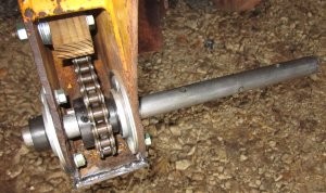
I had already replaced the bearings, chain, and center of for the auger.
Notice the wooden block that is used to adjust the chain tension in the left picture above. That definitely dates it as a 1960’s thing!!
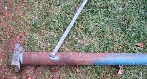
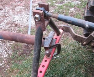
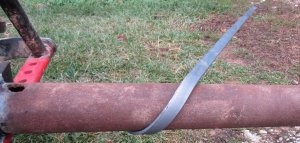
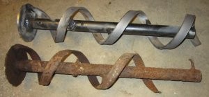
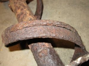
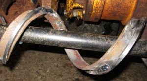
The auger used on the ground saw did not use the flighting that’s generally associated with an auger. Instead, the auger consisted of a 4 inch O.D. spiraled section of ¼” by 1 inch flat stock. It’s barely noticeable in the picture of the rusted auger, but there’s also a smaller section of flat welded to the 1 inch section. I had an idea how I could make the spiraled section. I welded a 5 foot section of ¼” by 1” flat to a 3 ¾” O.D. pipe at the angle of the spiral.
I had previously welded a section of 4” channel to one end of the pipe. I used this channel to secure the pipe to my tractor drawbar.
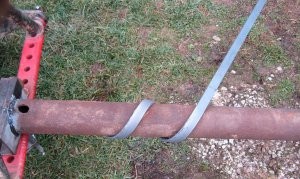
With the pipe secured to the drawbar, I “wrapped” the flat around the pipe.
After 180 degrees of wrap, I had to flip the pipe over. It required a lot of work and the use of a large hammer to keep the section flat against the pipe.
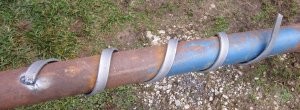
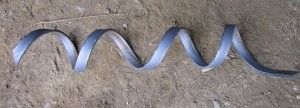
It wasn’t as easy as I thought it would be, but I soon had my spiraled section.
I cut the section loose from the pipe and slid it off the end.
The loops weren’t as uniform as I had hoped. The first loop had a 6 inch lead and the second loop had a 6 ½” lead. But, when I checked the original dirt auger, it too had a 6 inch lead for the first loop and a 6 ½” lead for the second loop. I couldn’t measure the third loop on the original auger since it was rusted away. I decided to wait to cut the auger to the correct length after it was welded in place.
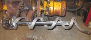
I machined a 4 ¾” O.D. disk with a center hole that would fit over the auger tube I’d installed earlier. I welded the disk in place and slid the spiral section over the tube. After several attempts I managed to find a way to center the spiral section on the tube using several appropriately placed wooden blocks.
The dirt auger that I’d removed had 4 short sections of ¼” by 1” flat welded between the spiral section and the center tube that kept the spiral section centered. I cut 4 sections, ground them to fit and welded them in place.
I managed to find some pictures online to determine an approximate length of the dirt auger and cut it to the length I wanted.
The auger had a ¼” by ¼” strip welded around the spiral that I still needed to add.
I located a ¼” by ¼” piece of square, steel stock to complete the dirt auger. The piece was relatively easy to bend around the auger, but it kept wanting to twist as I wrapped it around the auger. I had to use a wrench to keep twisting it back to keep it flat against the auger. I felt the welds to hold it in place messed up the looks of the auger but think when it’s all painted they won’t be so noticeable.
I mounted the auger back on the GroundSaw using three 5/16 inch bolts to hold it in place.
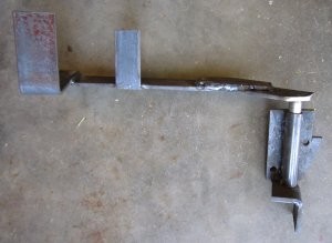
I thought I was finished and ready for painting, but found two more improvements that I needed to make. As mentioned previously, the hydraulic drive system for moving my Cub Cadet around was either “on” or “off”. Besides requiring even more weight on the front end, the tractor was difficult to maneuver while holding a hydraulic valve engaged. Since the GroundSaw can be moved around with its own hydraulic drive system, I hadn’t planned to install a driveshaft and clutch in the Cub Cadet. Hawk Bilt designed the GroundSaw to leave the clutch in the tractor. In operation the clutch pedal had to be locked down to permit movement using the hydraulic drive. This also required that the Cub Cadet brake be disconnected from the clutch and an auxiliary brake installed. Since moving the tractor around with the hydraulic system proved to be so cumbersome, I installed the clutch, disconnected the brake, and manufactured and installed an auxiliary brake.
And finally everything was finished and ready for painting.
