Note: As you read through this article you’ll notice that I have places where I need to post additional pictures. As I get those pictures I’ll add them to the article.
I’ve seen a lot of questions about the narrow frame hydraulic pumps that Cub Cadet used on their garden tractors. I’ve worked on quite a few of these so I thought I’d write an article on what I know about them. Fortunately, I don’t have one that needs working on right now, but I’ll use pictures and information that I’ve gained in the past for this article. The next time I have to work on one, I’ll get some pictures as I go – if I don’t get in too big of a hurry as I usually do!! The pumps generally don’t show much wear but require replacement of two seals that start leaking over time. The major fault is the failure of the pump gears. This is often caused by the failure of the valve return spring. If a section of the spring breaks and works its way into the gears, the gears are toast. For that reason, if you have reason to suspect a spring failure, quit using the pump and replace the spring.
The pump used on Cub Cadet was apparently manufactured for Cub Cadet by Hein Werner. These pumps with some major and minor variations were used on a variety of garden tractors. I’ve collected pumps from Toro, Wheel Horse, and Bolens as well as Cub Cadet. I’ll include some pictures and discussion about these variations after talking about the overhaul rather than making this discussion too long winded. (The Wheel Horse discussion got so long that I’ve moved it to it’s own section.)
A good friend, Larry Goss, sent me some additional information after I first wrote this article that I’ve since included in my discussion. Larry has a Hein Werner pump on a Power King tractor.
Begin by removing the pump from the bracket assembly.
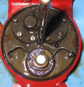
Begin the process by removing the nut that holds the reservoir in position. The nut is No. 52 in the previous parts diagram. Part No. 53 in the diagram is a washer and seal that seals the end of the hydraulic reservoir. On the majority of pumps I’ve worked on, this seal is stuck to the end of the reservoir. Don’t try to slide the reservoir off. Rotate it so that you “unscrew” the seal from the threads so that you won’t mess it up. The seal is one of those NLA things.
I’ve only had to remove the valve (No. 30) on one pump that I’ve worked on. Generally I’ve found that this part doesn’t leak. If you have to remove it, I think it’s easier to remove the external snap ring and force it inward rather than trying to remove the two roll pins on the inside. But be aware that the valve and pump body are made of mild steel and it’s easy to mar the surfaces. If you’re going to remove the valve, unscrew the control arm from the valve body and carefully remove the return spring on the inside surface. After removing the snap ring thoroughly clean the outer end of all paint and debris. I used a plastic mallet to gently tap the valve inward on the one that I did. I ordered a new O-ring from a Cub Cadet dealer (Part Number IH-707253-R1 1-1/4 X 1-1/2 X 1/8 O-ring). I do know that it was a tight fit and the valve was much stiffer after I replaced the O-ring. (Larry tells me the O-ring is an Amp-121.)
The three things I replace are the drive shaft seal (47), the reservoir gasket (35), and the valve spring (41).
The valve spring is NLA from Cub Cadet, but there are several places that now carry a replacement — Part No. IH-386371-R1. (You can find them from many of the sponsor’s of IHCubCadet.com. This spring can be also be ordered from JC’s Farm &Garden Supply mentioned in the Wheel Horse article. They also carry replacement gears. They have the replacement spring for the pump used on Cub Cadet, Part No. 5281.)
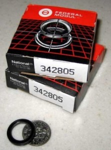
I replace the shaft seal with two seals as sort of double insurance.
The seals are small and it’s easy to get two of them in the shaft bore. But be careful you don’t push them in so far they cover the return drain hole located at the back of the bore. You should be able to pick up the seals at any bearing supply store.
Since the reservoir seal is also NLA from Cub Cadet, I use a replacement from McMaster Carr. Order: http://www.mcmaster.com/#catalog/119/3482/=l3rdnd , Item No. 4061T269.
They’re a little taller than the original seal, but they work well.
 There’s two gears that pump the oil through the pump. One gear is connected to the input shaft, and the other is an “idler” gear. I’ve never had to replace the bearing in the idler gear, but Larry tells me it’s an Oilite bushing ISO B060806. It seems to me since this gear runs in oil, a solid bushing should work just as well, but with the part number listed any bearing supply store should be able to come up with the necessary dimensions.
And that’s about it for now until I have to rebuild another one and get some more pictures. Don’t forget to “screw” the reservoir back on to avoid ruining the seal. And, by the way, I also figured that if I screwed up that seal, I’d just cut out a new one from neoprene and back it up with a flat washer.
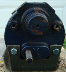
I mentioned earlier that several tractors used the same pump. In most cases the “guts” of the pump are basically the same, but the mounting is different. If you want to use one of these other pumps as a replacement for your tractor, make sure it turns in the correct direction. Several garden tractors use a pump that turns in the opposite direction of the one used on the Cub Cadet. You’ll notice on the pump end there’s an arrow that indicates the direction the pump must rotate to operate.
The picture above is a Wheel Horse pump. Notice that the input shaft is on the right and indicates a counterclockwise rotation — the same as a Cub Cadet.
I don’t know what brand of tractor the pump above belongs to, but notice the input shaft is on the left and the arrow indicates a clockwise rotation.
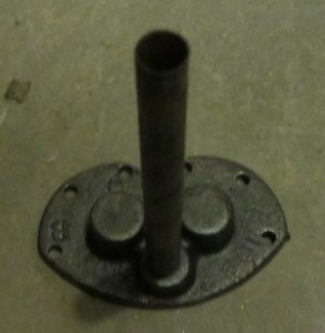
I also had a pump that had a tube fastened to the return inlet.
The long tube seems like a good idea to me since it would prevent a broken spring from getting into the gears. I don’t know what kind of garden tractor this pump was manufactured for, but notice in the right hand picture that this bracket is made for a pump that rotates in the clockwise direction and won’t work on a Cub Cadet.
There’s another difference that I’d forgotten about, but Larry reminded me. One of the hydraulic pumps I worked on had needle bearings for the input shaft. All the Cub Cadet pumps I’ve worked on had a steel input shaft in a steel bore. Larry tells me that all Power King pumps contain needle bearings.
 You should be able to make out the needle bearings in the picture above. (You might also just be able to make out that oil return hole on the right hand side of the bore that I mentioned earlier.) Larry tells me that a replacement needle bearing is a Torrington Bearing KOYB88.
As always, if you have any questions or comments you can contact me through this website.


