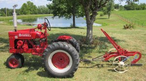
Note: There’s a video of the finished plow being pulled by the Mini-H under the Special Projects in the Video Section of this website.
Building an IH Plow
Even before I started working on the Mini H, I knew that I wanted to make a plow to pull behind it. Rather then take pictures and measurements of an actual plow, I purchased a plow manual at an antique iron show. The thing that was really neat about this manual was that not only did it have set up and usage directions for the plow, it had a complete parts breakdown. The manual had enough pictures, illustrations and details that I could determine the scale of several dimensions that I wanted. (A copy of that manual can be found in the Manual section of this web address, but, be warned, the high resolution version is very large to download.)
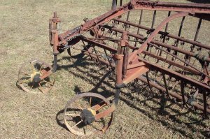
I had been looking for wheels for some time and found what I needed on a Case side delivery hay rake.
As an added bonus, the rake contained several levers that looked like they could be used for the plow.
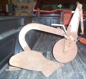
I had three different plows that I could use as a starting basis. One was a Sears 3-point hitch plow, one was a Wheel Horse plow, and I think the other might have been a David Bradley. I wish I’d taken a picture of the setup I used to determine which plow to use, but, again, I got in too big of a hurry. I parked the Mini H in my shop, ran a piece of PVC pipe through the two steel wheels, and placed them behind the H at what I thought was the correct distance. One at a time, I placed each plow behind the steel wheels with a piece of 2 inch sheet metal channel running from across the top of the plow to the H drawbar. With this setup I could get a good idea of what the final plow would look like and determined that I wanted to use the Sears plow.
I unbolted everything that I could and used a torch to remove the rest so that all I had remaining was the point, moldboard and beam. Notice in the picture that the way the plow is made, the beam tends to angle downward as it goes forward. I eventually had to correct that.
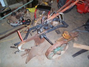
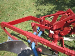
The first thing I did was make the main frame of the plow. The Sears beam was made of a piece of ½” by 2” flat iron. The frame I wanted to make had to extend downward at the front of the plow. So I decided it would be easier to make the frame of ¼” by 2” flat iron, make the appropriate bends and then weld the pieces together to get the ½” thickness. It’s not real clear in this picture, but you can see where the frame extends forward from the beam of the Sears plow. (The rusty section is the Sears beam.) The right hand section of the frame consists of the two pieces of ¼” material welded together and the left hand side is only ¼” thick. The frame has a width of 7 1/2″. On the right hand side, the frame extends 11″ forward of the Sears plow frame and then bends downward for 8 1/2″ at a 70 degree angle.
Next I had to bend the plow axles. Usually when I bend steel, I use a saw to cut half way through the thickness along the inside axis of the bend. Since the metal being bent tends to compress and get thicker on the inside of a bend, this allows for some room for the compression and makes for a much cleaner looking bend. After the bend is made, I run a bead of weld along the cut to close it. But when I tried that method with the 1 inch diameter axles, it didn’t work. It made an awful looking bend. So for the round material, I just heated the metal and bent it. Surprisingly to me it made a nice looking bend.
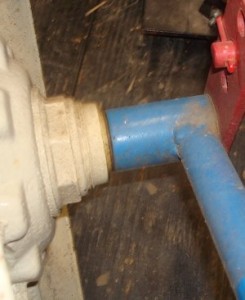
The left axle was a pretty simple bend since the end of the axle contained a bearing housing. It just required one right angle bend at the top. It is 9 1/2 inches from the center of the bearing support to the center of the bend at the top.
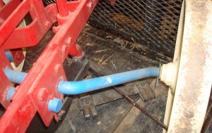
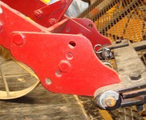
The bracket welded to the top, horizontal section of the axle determined the final position of the axle. Notice the extra holes drilled in this bracket welded to the left axle in the picture on the left above. Those were there in case my scaling was off. The right axle wasn’t as bad to make as it looks. The two ends sections had to be parallel to each other. The hard part was getting the bend at the correct angle. And, I’ll admit I did a little guessing here. Once one end was bent it was a simple matter to bend the other end parallel. The axle is 10 inches long measured perpendicular to the ends. The angle is close to 70 degrees.
(In the upper left center of the picture above, you might be able to make out where I’ve welded over the cut that was made to produce a bend in the main frame.)
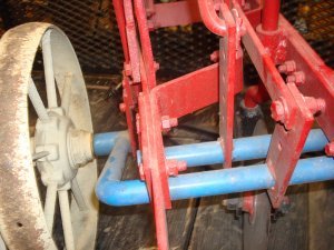
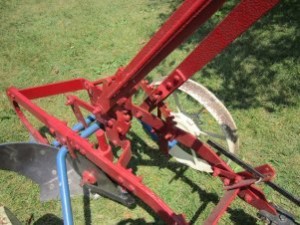
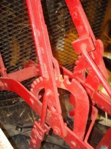
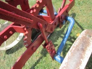
With the major parts of the main frame made, it was a simple matter to make several supporting brackets to hold the axles in place. In the above picture you can also see where the rolling cutter is attached. The manual did a good job of indicating where both the control levers of the plow had to be mounted. One of the levers I got from the Case rake had to be shortened for use on the right side and the other had to be lengthened for use on the left side. You can see in the picture where the original pivot hole for the left lever was located. You can also see where I had to add a bracket to the right lever to connect the lifting arm.
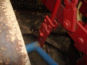
If you’ve ever used a pull type plow, you know there is a trip mechanism that drops the plow and another mechanism that raises it. I have an idea of how I want to do that, but have never gotten around to it. For safety I made a bracket to hold the plow in the raised position.
You can see in the above picture I’ve added a bracket with two bolts holding the plow in the raised position. I can promise you that if I take out those two bolts, the plow will trip!!
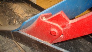
I mentioned earlier that the moldboard was at the wrong angle when I placed the plow beam horizontally. I welded a piece on top of the beam and redrilled the hole for the moldboard.
You can see in the picture the added bracket and the hole where the moldboard used to be mounted. As an added touch, I used my CNC mill to make the front adjusting brackets.
I thought it added a nice touch to the finished product and looked like the brackets on the original plow. Notice that the holes are located on a radius so the angle can be adjusted.
And that’s it. The rest of the plow was simply pieces of flat iron cut to length with the appropriate holes drilled. I was pretty happy with the finished product. And, no, I’ve never tried plowing with the plow. It’s been strictly used for show. But I have little doubt in my mind but what it would work perfectly.
As usual, if you have any comments or questions, you can contact me through this website.
