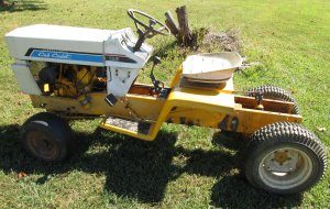
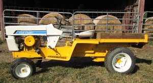
We’ve owned Cub Cadets since 1978. We first purchased a Model 122 and a short time later added a Model 102 to mow our lawn. (It’s a large lawn.) My wife wanted to use one of our Cub Cadets to do garden work so I built her a small trailer to haul flowers, plants, fertilizer, weeds, etc. Since we have a lot of fenced pasture, the trailer also turned out to be handy for hauling fencing supplies. At first, I would load and unload fencing supplies every time I needed to repair or replace fencing. As our fence got older and required more repairs, more and more supplies were left on the trailer. It eventually became a dedicated trailer for fixing fence and my wife no longer had the use of it for gardening.
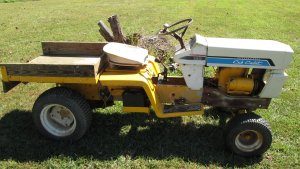
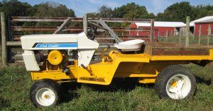
My wife made it clear that she was in need of some kind of vehicle to use for gardening. I originally purchased a 1650 roller and a 129 roller and made an extended Cub Cadet with a bed on the back for her to use. The 1650 originally had only one headlight so she called this stretched tractor “Wink” and the name stuck. But it was a hydrostatic drive and after using Wink a couple of times my wife parked it and said she wanted me to rebuild it as a gear drive.
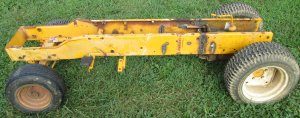
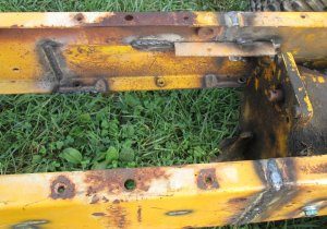
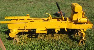
It took some time (several years), but I eventually obtained the parts, time, and inspiration I needed. I wanted to stick with a wideframe so I could use as many parts from the original Wink as possible. I eventually purchased a 128 parts tractor at a local auction and a good friend, Paul Brosmer, furnished me with two 21 inch long, wideframe extensions. I welded the extensions to the 128 frame. I used two short sections from a narrow frame to reinforce the bottom of the welded joint.
If I had it to do over, I would’ve done one thing differently. I C-clamped the short, narrow frame sections to the wideframe sections to hold everything in alignment before welding. After I got everything welded and tried to install the rear end, the mounting holes were off just a little bit. I just drilled them a little oversize and everything fit. But, if I had it to do over, I would’ve installed the rear end once everything was c-clamped in position so that I could make some final “tweaks” before welding.
Installing the front axle and steering mechanism made Wink mobile so it could be moved in and out of my shop. I installed the 10 hp engine from the original Wink and I was ready to start the transformation. I felt the clutch, drive shaft and brake would be the easier parts of the project so I began with those.
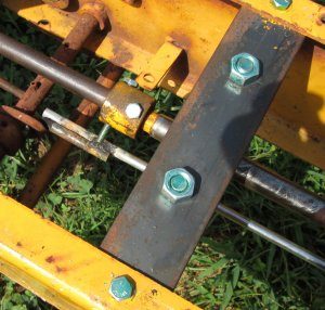
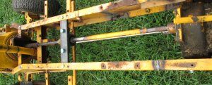
I had removed the clutch from the 128 parts tractor when I purchased it and still had all those parts. The clutch plate and teaser spring needed replacing, but I’ve done several of those and had spare parts on hand. After rebuilding and installing the original clutch, it was just a matter of making an extension that would reach back to the new location of the transmission. Experience had taught me that a drive shaft of that length required some sort of additional support. I bolted a pillow block bearing to a section of flat and bolted the assembly across from side to side in the frame. It took a little time, spacers, and adjustment to get the bearing located so everything was in alignment.
I cut the original brake rod in two and welded each half to a length of ½” rod. Mounting the longer rod completed the brake assembly– probably the easiest part of the conversion.
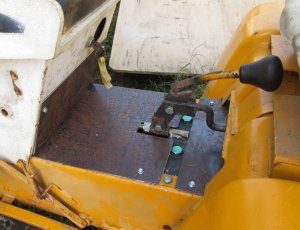
With the “easy” stuff done, I turned my attention to the shift mechanism. I had spent a lot of time thinking about different ideas for an extension and had received an email from a fellow collector suggesting that one of my simpler ideas would probably work. The new gear shift had to allow for movement both forward and backward as well as side to side. The side to side motion was what concerned me most. There couldn’t be any twisting in the mechanism or it wouldn’t shift.
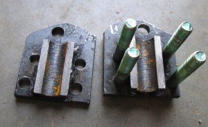
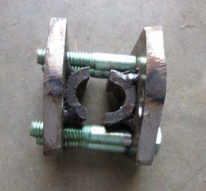
I cut the original gear shift lever off about an inch and a half above the spring. I didn’t want to weld to the shift lever in case I had to disassemble it if any future repairs became necessary. I manufactured a bracket that would clamp securely to the shift lever and not permit any twisting.
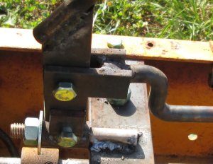
The assembled bracket left enough room to install a short section of tubing across the top between the two sides. A ½” rod welded to the tube extended forward to the front shift lever.
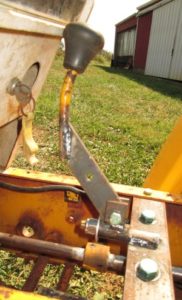
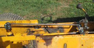
With the bracket for the back completed, I turned my attention to the front shift lever. The lever had to pivot forward and backward as well as side to side. After installing all the sheet metal to be certain there was sufficient room, I welded a bolt extending forward from the cross member I had installed to mount the pillow block bearing. Sliding a piece of tubing over this bolt provided a means for the side to side motion. Welding two tabs to the tubing provided a mount for the shift lever and allowed for the forward and backward motion. The extra width of the bottom section of the shifter wasn’t to add strength but was necessary to prevent any twisting motion in the mechanism.
Connecting the back bracket to the front shift lever with the ½” rod completed the job. The new shift lever was 31” forward of the one it replaced. The dog leg in the rod was necessary to allow for clearance under the fender assembly.
I wouldn’t classify the way the mechanism shifts as “great”, but it is “very good.” You can’t speed shift. It just requires a little patience to get the correct feel for the shift. Overall I was very pleased with the results. (Hope my wife feels the same way!!)
Remounting all the sheet metal and completing the wiring allowed me to take a test drive.
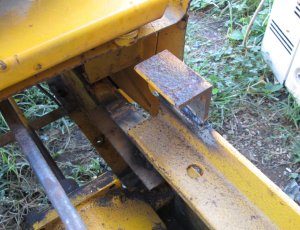
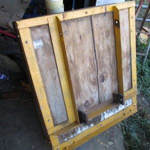
The hard part was done. Next it was just a matter of mounting the bed and the second generation Wink would be ready to go. For the original Wink, I had installed two pieces of angle that extended 6 inches behind the Cub Cadet frame to permit a larger bed. It also resulted in a lot better looking, better scaled tractor. I bolted these same two pieces of angle to the new Wink and determined the bed had to be mounted two inches higher to clear the rear shift mechanism. I welded a short section of 2 inch angle to the front of each angle that I’d bolted to the frame for the front of the bed to sit on. It also required an extension to the rear bed mount to raise it the required two inches.
When I mounted the bed to the rear of the new Wink, I had plenty of clearance for the shift mechanism.
Finally it was just a matter of making some covers for the frame where the drive shaft was exposed before I could do any painting. Because of the limited room, I could only install a couple self tapping screws in each cover, but more screws could be added when the tractor was disassembled for painting.
With everything completed it was time to clean and paint Wink and let my wife try out the finished project. Since this was not going to be a “show” tractor”, I took the easy way out and left most of the tractor assembled for painting. That’s not a good idea if you want a professional looking paint job.
The final project was one of those 15 foot paint jobs, but after a couple weeks of work there will be enough dust and dirt that no one will notice. And, my wife is happy with it and that’s what counts!!
For anyone interested, there’s a video of Wink in operation in the Video Section of this website. As always, if you have any questions or comments, you can contact me through this website.
