I had never considered writing an article on building the Mini New Holland rake. After all, I had built it approximately 20 years ago, and I didn’t think I had any records left from the build. But after someone emailed me and asked if I had any of that information, I checked through the archives (stacks of folders and notebooks) and found I did still have a file folder with some information in it. But since this was done before I had access to programs that automatically generated G-code, the folder consisted of only one computer drawing and it was pretty crude. All the G-code had to be generated “by hand” so the folder consisted mainly of a lot of position calculations. But I’ll try to put together some kind of description for anyone that’s interested. If you’re not actually interested in building a small rake, this article won’t be of much interest to you. And, one other thing, when I built this rake it was with the intent to use it. It wasn’t built as a show piece so I didn’t grind any welds and just cut stuff off the easiest way possible. I’ve since purchased an EZ-Vac system, and the rake is only used to take to shows. I wish I’d had that in mind when I built it.
Note: My wife found three original pictures that she took when I was building the rake. I’ve now scanned them and added them to the article.
Before I start the description, I need to define some of the terms I’ll use. I’ve gotten smarter in later projects and purchased parts manuals so I could use actual parts names, but that was not the case for this project. So, here’s the vocabulary I used:
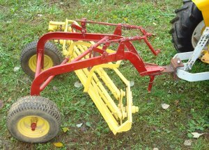
Frame – the main frame consisting mainly of the two long sections of channel that extend across the top from the tongue to the rear axle.
Basket – basically everything that’s painted yellow except the wheels. It consists of the parallel rake bars and the frame that holds them.
Basket frame – the part of the basket that supports all the rotating parts.
Bars – the five bars that contain the rake teeth.
Stars – the star shaped section on each end of the basket that rotates and keep the bars parallel.
Bar ends – the very end pieces that connect the bars to the stars.
I began the process by filming an actual rake. We did it with three people. Two people held a measuring tape and called out dimensions while the third person filmed making sure they recorded both ends that were being measured. The original tape was transferred to a VHS tape that I could replay to get measurements. Those measurements were used to make some of the crude sketches that you’ll find in this article. The mini-rake was made as close to one third scale as possible. Unfortunately that VHS tape has long since been recorded over and no longer exists.
With the measurements known, I made up a parts list and ordered the parts I’d need.
You can tell by the prices that this was a long time ago!!!

The first step in the process was to make the frame. That turned out to be one of the two most difficult parts.
I found the dimensions I used on one of my sketches.

Notice in the sketch that the parts have not yet been scaled. (I probably “used up” the sketch with the scaled dimensions as I was making the rake!!!) These two frame pieces are made of 2” channel as per the parts list. Notice the back section is a 90 degree bend. It’s nearly impossible to bend a channel that much but we managed. Unfortunately the jig that I used to make the bends no longer exists. But it consisted of a heavy steel frame (several 8” channels welded together) that I welded two vertical pieces of tubing to. I heated the 2 inch channel where I wanted to make the bend, placed it between the two vertical pieces of tubing and pulled to bend it into position. When you bend channel like this, the inside web will buckle and the outside section will stretch. But, since I was making this to use, not show, I didn’t care. I beat everything into flat the best I could while it was still hot and used the welder to “thicken” the stretched sections.

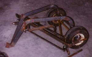
This is one of the original pictures my wife located. Notice it must have been cool weather when I was building the rake. Also, notice the front sections of the frame are still longer then they need to be. I later cut them off. In the picture I’m grinding down some of the weld that was used to build up the frame section after it was bent.

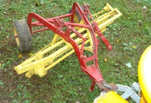
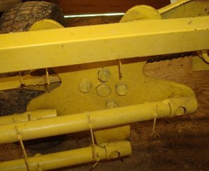
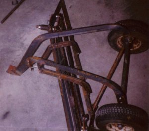
With the frame bent and welded in position, I drilled a clearance hole in the rear of each section for the axle and welded a section of tubing that would hold a 3/4″ I.D. ball bearing. You can see a small section of the tubing in the picture below. I also added some cross braces as you can see in the pictures above. The wheels are one of the things not to scale. Since I wanted to use the rake in our yard, I wanted wheels that were large enough to give a smoother ride. The larger then scale wheels produced some problems when I got around to connecting the drive mechanism.

Next I turned my attention to making the basket. I decided the easiest way to do it was to make the stars and attach the bars to hold everything in position as I made the frame. I cut the two stars on a CNC mill. Below are the sketches I found in my folder.
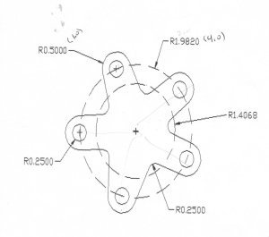

The drawings probably look a little confusing. The one of the right shows the outer outline of the star. It has an outer diameter of 10 inches. The holes are located on an 8 inch diameter. The sketch on the right shows the locations of the hole centers.
Besides the five holes where the parallel bars attach, there are four holes to mount a center hub. The center hub bolts to the star and contains a ¾” shaft that is used as a pivot for the star. I should mention that the stars are made of ¼” material and the holes for the bar connections are 3/4” in diameter. The four bolts to mount the hub are 5/16” diameter on a 2 “ diameter. The hub is a 3” diameter. I also made ten ¼” thick washers with a ¾” bore to weld to the outside of the stars to provide more bearing service where the bars connect.
With the star ends made, it was time to work on the connections (bar ends). I think the connections on a full size New Holland rake use ball bearings, but I’m not sure. I do know that using ball bearings made the ends to large and cumbersome for my application. I don’t know if I considered needle bearings – it’s been 20 years ago – but I settled on brass bushings. I inserted flange bearings (3/4” O.D., ½” I.D.) in each of the outer holes in the star.
To make the bar ends, I began by taking 1” bar stock and turning it down to .709” (the I.D. of the tubing for the bars) for 1.5 inches. I made a fixture that I could slide the stock into and mill a flat at 20 degrees. (I made a model on the computer to better illustrate the fixture for this article. I didn’t have the luxury of having a modeling program when I originally built the rake.)
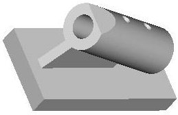
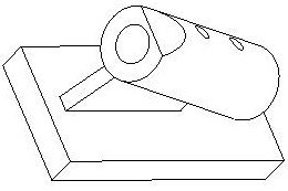
The fixture was made by boring a .709” hole in a piece of 1” round stock and welding the round stock to a flat plate at a 20 degree angle. Notice the two smaller holes in the fixture. That’s for two set screws that hold the bar stock in position after it’s inserted. I milled a flat and a ½” “oval” hole in each of the ten end pieces. After milling the flats and holes, I rotated the fixture 90 degrees, reinserted each of the ten pieces (one at a time) and drilled a 1/8” hole through the side of each piece.
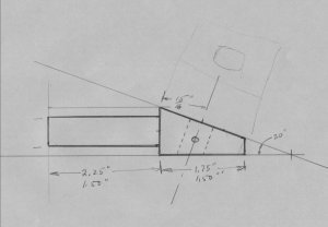

The picture on the left is my original sketch, and the one on the right is the model I just made to illustrate the finished part. If you have a keen eye, you’ll notice that the ½” hole is somewhat oval. I did that to allow some “wiggle room” when I installed a ½” diameter shaft through each of the holes. In that way, the alignment wouldn’t be quite as critical.
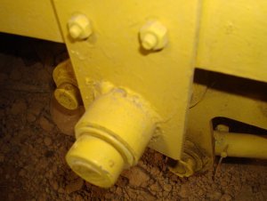
I drilled a 1/8”hole through a section of ½” cold rolled, inserted it into the bar end and fixed it in position with a 1/8” roll pin. While I don’t have a picture of the finished product, I did make a model on the computer to illustrate what it looks like.

One end of the bar end is pressed into the 7/8” tubing. The ½” rod extending from the side of the bar end extends through the brass bushing in the star. On one end I placed collars with set screw over the rod to hold them in place and on the opposite end I used a washer and cotter pin. I remember there was a reason I used the two different methods to secure the rods in place (20 years ago), but the reason now escapes me. Much later, the bar ends were welded to the bars. As a reminder, the finished product looked like this:

According to my notes, the bars were 33 inches long from the center of the 1/2″ rod on one end to the center of the 1/2″ rod on the opposite end.
The center hubs were 3″ diameter and made from 1/4″ flat. The four bolt holes were located on a 2″ diameter circle and a 3/4″ hole was cut in the center of the hub. A 3/4 shaft was inserted in the center hole and welded in place. The center hubs were then bolted into place on the star, and a mount was fabricated for each end.

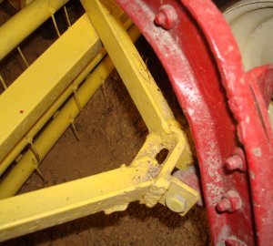
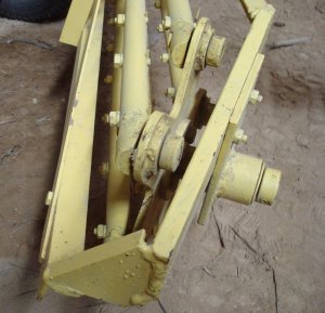
Notice the end support consists of a piece of tubing welded to a piece of 1/4” flat. Each end of the tubing contains a 3/4” I.D. ball bearing. The entire support is bolted to a 2” channel. I don’t remember at all how everything was aligned to weld the basket frame together. I’m sure it required the use of a lot of clamps and extra supports. With the bar ends all inserted in the stars and the hubs attached, the rotating parts of the basket were basically in the correct position. So, it was a matter of welding together a frame to hold everything in place. I do recall that on the original rake there were a lot of curved sections in the frame that I could not duplicate. I used several straight sections in their place. And, I do recall that I was delighted when everything rotated and stayed parallel when the frame was finished even though it was rather stiff. I mounted a pulley on one of the hub shafts and used a v-belt drive to a speed reducer to let it rotate all day to loosen things up. It now rotates very freely.
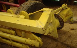
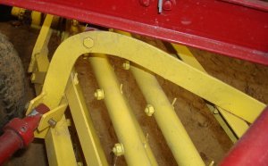
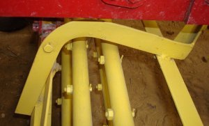
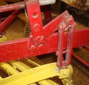
It was pretty easy to duplicate the “suspension system” that connected the basket to the main rake frame. There are two curved angle sections that bolt to the basket frame and connect by a pivot at the front to the main rake frame.

Like the 2” channel, the angle was a little difficult to bend, but I managed. Again notice in the picture below that these are not the scaled dimensions.

The back of each of the angles can be lifted by hand cranks used to level the rake basket from side to side. The only sketch I could find of this lifting mechanism was the brackets used to mount the back pivots to the main frame.

The bottom sketch is the scaled drawing. The lift mechanisms were pretty easy to duplicate. I couldn’t find any other sketches of the dimensions.
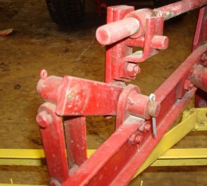

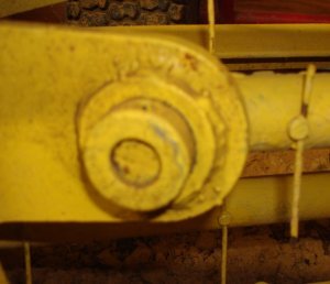
I used an eye swivel to connect the two angle pieces at the front of the basket to the frame.
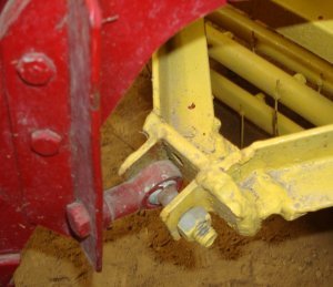
Notice again this was just welded up to work. I think I may have even used a torch to cut the metal to length after welding. I wasn’t trying to make it look pretty.
Now, all that was left was the drive system. When I’d attached the rear wheels, the left rear wheel was pined to the rear axle and the right wheel was allowed to turn freely to provide a “differential” action when turning corners. Since the wheels were larger then the 1/3 scale used for everything else, it was not possible to run a drive shaft from the center hub to the rear axle as it was on the original rake. I considered some sort of pulley arrangement like used on some John Deere rakes I’ve seen, but I wanted a positive drive. (Guess that’s why I’m a Cub Cadet guy and not a John Deere person!!) I used a chain drive to move the drive further away from the axle and used a Craftsman right angle gear drive as the gear box to make the right angle transition.
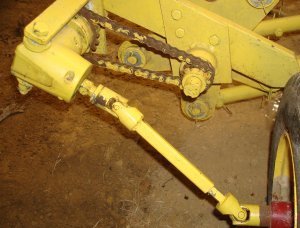
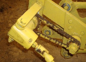

I don’t have a clutch in the system. I remove the u-joint connection from the wheel to move the rake around without basket rotation.
The tongue and a makeshift “jack” were easy to add.

The last step was to add the rake teeth. I spent a lot of time looking for something that would simulate the actual rake teeth but couldn’t find anything. I finally decided to use piano wire. It’s been too long to remember what size wire I ended up using. I made a fixture to make the bolts to support the piano wire.

To use the fixture I clamped it in a vice in my drill press. I inserted a 1/4″ bolt through the end and used the small hole from the top as a “pilot” hole to drill a small hole through the 1/4″ bolt. I then removed the bolt from the fixture and cut the head off. A section of piano wire was put through the small hole in the bolt and the bolt was installed in one of the bars. Placing a nut on the bolt allowed it to be tightend to the piano wire. After drilling several of the small holes, the hole in the fixture would become “wollered out” and I’d have to make a new fixture.
A finished rake tooth looked like this:

The piano wire bends a little easier then I would like, but it works.
The first time I tried it out was on some dry grass. I was pleased with the results. It wasn’t as good as a vacuum system, but it sure beat hand raking.
If you’re familiar with a New Holland rake, you’ll notice one thing is missing. There should be several “rods” that wrap around the bottom of the bars from the front of the basket to the rear. I didn’t think these were important before I started using the rake. But I was wrong. If the winrow gets too large, it will tend to wrap around the basket bars as they rotate. The rods would tend to “wipe” the hay from the bars.
And that’s it for now. Sometime this winter when I have more “indoor” time, I hope to darken up the sketches included in this article. If I think of more, or if someone requests additional information, I’ll add it. As always, if you have any questions or suggestions, please contact me through this website. Hope you find the article useful.
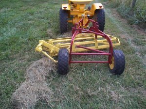
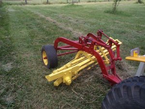
Someone emailed me and asked for some additional pictures so they could build their own rake. A lot of them are redundant of what’s posted above, but I’ve included them here with no additional explanation in case anyone else is interested.


As always, you can contact me with any questions or comments through this website.
