While I really enjoyed building, showing, and driving a hydrostatic driven, articulated Cub Cadet (Artie I), I really prefer gear drive machines. So, I completely dismantled Artie I and rebuilt the machine as a gear drive (Artie). I wrote an article on the build that appeared in the 2014, Jan./Feb. issue of Lawn and Garden Tractor magazine. It’s a fantastic magazine, and a link to their website can be found in the Favorite Links section of this website. To keep that article a reasonable length and hopefully make it of more general interest, I left out several of the smaller details of the rebuild. After that article was published, I added some of those details here. What I’ve added won’t make sense if you haven’t read the article, so hope you’re a subscriber or pick up a copy of the magazine if you’re interested in the build.
Here’s what Artie I now looks like:
I also have the hydrostatic drive for the rear end, but it’s removed in the picture.
There’s a video of Artie in the Special Projects Video’s under the “Videos” section of this website.
We had some bad weather during December, so I took the opportunity while I was stuck in the house to write the article on the details I’d left out of the L> article. Those details are given below.
Rear Frame
I cut the rear frame so that it was 25 inches in length. I notched out the frame at the 6 inch point and bent each of the 6 inch sides in so that I had a 2 1/2 inch space in the center between the two sides. The rear axle was mounted using the original mounting holes in the frame. The rear fenders are also mounted in the original mounting holes.
Front Frame
The front frame is 47 inches long with the centerline of the axle located 21 inches from the rear of the frame. The 47 inches is an approximation since the front of the frame isn’t square. I had to drill new holes to mount the front axle.
Concerns
I had (and still have some) concerns about several aspects of the project. The biggest concern was the extended top shaft. My biggest concern is/was with the gear teeth on the top shaft. I don’t know how the gear teeth will hold up after being subjected to the heat generated when welding on the extension. Secondly, it’s a minor concern, but I think the needle bearing that supports the top shaft will hold up. Originally, it only supported the “non-loaded” end of the top shaft. Reversing the transmission means it’s now on the loaded end. I’m a little concerned about an oil leak around the needle bearing seal. However, I did leave room that I can add a “collar” and install a larger seal if necessary. Also, there could be an oil leak under the “sliding” plates, but so far that hasn’t been a problem. I think the heavier oil is helping that situation.
Steering pressure
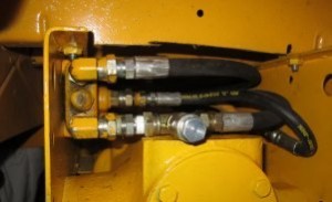
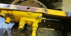
To check the hydraulic pressure in the steering, I placed a pressure gage at the entrance of the hydraulic valve. By just turning the steering wheel, the pressure registered 300 psi. When I “bottomed” out the hydraulic cylinder, the gage registered 600 psi.
I didn’t get a picture with the gage installed, but you can see where I’ve plugged the port in the picture above. It’s on the lowest hose connection.
I purchased a Prince, compact, adjustable relief valve from SurplusCenter. The gage originally was adjustable from 1000 to 2500 psi and preset to 1500 psi. I replaced the original spring with a piece I cut off the end of this spring.
I wanted to show a picture of the spring I took out for comparison purposes, but I laid that spring up in a “safe” place and can’t remember where I put it!!! I made the replacement spring about a half inch longer than the original spring. It’s not nearly as stiff as the original. I didn’t measure the length of either spring, and I don’t want to take the relief valve apart to measure it. With the replacement spring the gage showed a pressure of 200 psi whether I was just steering or bottoming out the cylinder.
Brakes
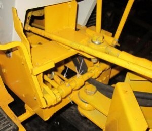
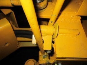
The brake linkage was the last thing I connected. The front axle is a Cub Cadet rear end with an internal brake. Just like a Cub Cadet the brake is activated near the end of the clutch travel. It’s difficult to get a picture of the linkage I used.
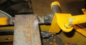
In the picture above, the larger arrow points to the bracket that connects to the shaft that activates the clutch. The smaller arrow points to the rod that extends from the bracket to the brake lever.
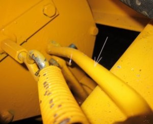
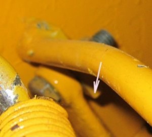
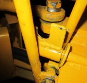
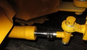
The picture above shows that same rod indicated by the large arrow. There’s a piece of flat (small arrow) welded to the end of the rod downward to the brake lever. Below is a close up view of that flat.
Gear shifts
Since Artie now has two gear shift levers, it would be possible to put the transmission into two gears at the same time. So I added a keeper that would keep one gear shift lever in neutral while the other was being used. The lever can be “flipped” from one gearshift to the other for shifting the transmission.
The picture on the left above shows the 2nd/3rd gearshift lever held in neutral. The picture on the right shows the lever in a raised position not constraining either shifting lever.
Steering mechanism
Artie I had a sharper steering radius than Artie. Artie I turned so sharp that it made it difficult to use the brake pedal. I limited the steering radius on Artie by placing stops on the hydraulic cylinder.
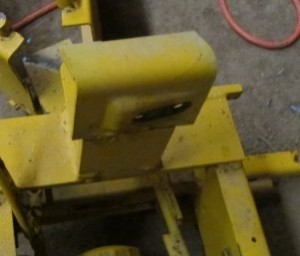
The steering gear box on a Cub Cadet is mounted at an angle to account for the fact that the drag link runs at an angle from the gear box to the front steering arm. For some reason on Artie I, I mounted the gear box at that same angle.
The picture above is the mounting on Artie I. Notice that the bracket is mounted perpendicular to the frame of the tractor, but the two holes for mounting the gear box are located at an angle to the bracket. I didn’t get a picture, but I mounted the bracket on Artie at an angle so that the hole locations were perpendicular to the frame, and the gearbox cam moves parallel to the frame of Artie.
I’ll repeat here the description of how the steering works from the article on Artie I with some pictures of Artie.
“Notice in the pictures that I had to add a pivot arm from the end of the drag link to the link that connects to the hydraulic valve. This pivot arm accomplished two things. First, it permitted proper alignment for the drag link from the steering arm on the front section of Artie to the pivot arm on the rear section of Artie. Secondly, it amplified the movement of the drag link. Previously, I had determined that it required a lot of rotation of the steering wheel to activate the hydraulic valve. By using a shorter distance for the top connection of the pivot arm then the connection at the bottom, it multiplied the movement of the steering arm and produced almost instantaneous steering wheel response.
Now the steering works something like this. Let’s assume we’re making a left hand turn. As the operator turns the steering wheel to the left, the steering arm pulls the drag link forward. The drag link pulls the top of the pivot arm forward moving the bottom of the pivot arm backward activating the control valve. The control valve sends hydraulic fluid to the cylinder causing Artie to pivot left. As Artie pivots left, the distance between the steering arm and pivot arm decreases and releases the hydraulic valve. To continue turning left, the operator must continue turning the steering wheel. Turning right is obviously similar except the steering arm pushes rather then pulls and the distance increases rather then decreases.”
Miscues
I made one miscue (that I know of) while building Artie. I assumed that since I rotated the front axle 180 degrees and left the engine in the original orientation, I’d have 3 reverse gears and one forward gear. So, I took the front axle apart and “flipped” the carrier gear before even first trying out Artie. Much to my dismay, the first time I drove Artie, I had 3 reverse gears and one forward. After a lot of thought, I finally figured out what was going on. If I’d rotated the axle 180 degrees and kept the rotation of the top shaft in the same direction by also rotating the engine 180 degrees, I would’ve had 3 reverse speeds and 1 forward. But, since I’d kept the engine in its original orientation, it now rotated the top shaft in the opposite direction of its original design. In other words, even though the transmission had been rotated 180 degrees, it was also rotating in the opposite direction of its original design. So I had to disassemble Artie, remove the front axle and flip the carrier back to it’s original orientation. I should’ve tried it out before flipping the carrier!!!
Future
Like Artie I, Artie is only driven by the front axle. But the final assembly has a straight, direct line between the “rear drive” of the front axle and the “front drive” of the rear axle. With a universal joint and a “pto shaft” the connection could easily be made. However, as with Artie I, I think Artie will only be used for display so that I’m not sure I’ll ever take the time and trouble to make that connection.
As always, if you have any questions or comments after reading the L> article or the information I’ve included here, you can contact me through this website.

