This is an article that was published in the 2014 Jan/Feb issue of Lawn & Garden Tractor Magazine — a great magazine that I highly recommend to any serious lawn and garden tractor collector. The article (More Articulated Gear Drive Cub Cadet (Artie) contains additional information I didn’t feel was appropriate for the original article.
In 2005, I built an articulated Cub Cadet (Artie) using a hydrostatic drive. I’ll refer to the original, hydrostatic Artie as Artie I in this article. While I really liked the looks of Artie I and enjoyed driving it, I just didn’t care for the hydrostatic drive. I’d thought about using a gear drive when I originally built Artie I, but had concluded, correctly, that the build would be easier using a hydrostat. After using and displaying Artie I for several years, I decided to try my hand at rebuilding Artie as a gear drive machine. (Several additional details concerning dimensions, decisions, etc. can be found in an earlier article I wrote concerning building Artie I. A copy of hat article can be found in the Special Projects section of Cubcadetman.com.)
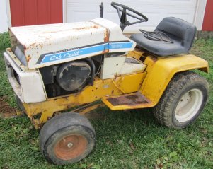
Since I had experience with Artie I, I knew the dimensions I wanted for the second Artie. A good friend gave me a Model 1000 Cub Cadet that I could use for the front section on the condition that I would remove the engine and return it to him.
I stripped down the frame and cut it to length. (I measured the lengths from the frame of Artie I. Most of those dimensions can be found in the article on Artie I.) As with Artie I, for the front section I reversed a Cub Cadet rear end, cut out the appropriate section of the frame and bolted the rear end in place.
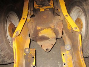
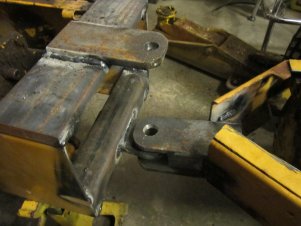
I welded a Category 2 end in a section of 2” by 2” tubing and welded it across the inside bottom at the rear of the frame.
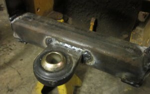
I welded a section of ½” by 3” flat across the top of the frame and welded a section of 3/8” by 2 ½” flat that extended back with a 5/8” hole centered over the Category 2 end.

I didn’t yet have a wide frame section to use for the rear, so I decided I’d temporarily use a narrow frame rear end to determine the dimensions I’d eventually use. I cut the two sides to length and bolted a Cub Cadet rear end in place using the original mounting holes. With the rear end bolted in place I could determine where to make the cuts to bend the frame inward. I bent both sides in to form the front of the rear section.

I measured the distance between the two sides and cut a section of 2” by 2” tubing to fit and temporarily tack welded it in place. The tubing was cut at an angle to match the angle of the sides of the rear section. I added two sections of 3/8” by 2 ½” flat to the tubing and welded them in place.
Since the narrow frame section I was using was only temporary, I made a temporary connection for the top, rear connection and used C-clamps to hold it in place. Adding a Category 0 top link completed the connection.
When I wrote this next section it became a little confusing since I kept referring to a “rear end” and was talking about the front section of Artie. To reduce some of this confusion, I’ll just refer to it as the transmission, and the reader will have to realize I’m referring to what is an entire Cub Cadet rear end that’s being used for the front axle.
Reversing the transmission and leaving the engine in the original orientation presented several problems. The “top shaft” on a gear drive, rear end does not extend out the back of the transmission. After the transmission was reversed the top shaft had to be extended forward to provide a connection for the drive shaft. Additionally, in an unmodified Cub Cadet the engine driveshaft is offset to the right. Reversing the transmission meant that the driveshaft was now offset to the left. Also, there was a very limited amount of space for the clutch.
The first task was extending the top shaft.
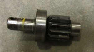
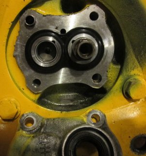
Unfortunately I only took a picture of the finished product, but I’ll explain what I did. I took the top shaft to a friend who’s a much better machinist than I am. He drilled a quarter inch hole in the stub end of the top shaft. He took a piece of ¾” cold rolled and turned the end down to fit in the hole in the top shaft to help center it. He also chamfered that end of the ¾” shaft to provide more welding surface. I took that setup to another friend who is an excellent TIG welder, and he welded the two pieces together. I took the welded piece back to my machinist friend and he turned the added ¾” section down to 5/8”.
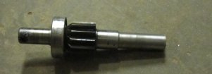
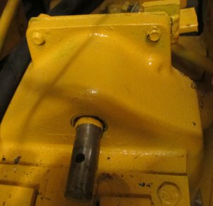
I replaced the original needle bearing for the top shaft with one that contained a seal and installed the top shaft.
With the top shaft extended the next task was to install the engine and clutch. I’d made some temporary measurements but needed an engine mounted in place to finalize everything. I removed the engine from Artie I and placed it in the new frame. I placed a 5/8” shaft in the clutch plate to get the correct alignment between the engine and the top shaft. The engine had to be moved so far to the left that I had to cut out a section of the frame for clearance for the points cover and dipstick.
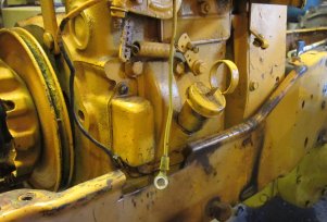
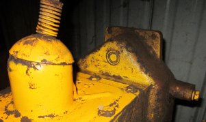
Also, with the engine mounted so far to the left, the original engine mounts couldn’t be used. I had found with Artie I that I preferred solid mounts for the engine. It took some time, but I eventually got everything figured out. I used two ½” by 3” by 10” flats welded to the frame to mount the engine.
It’s not obvious in the picture, but the front flat had to be a little higher than the rear flat to get proper alignment. I don’t recall the exact spacer (I tried several) but I think it was about 1/8” thick.
With the engine lined up and installed, it was time to look at mounting the clutch. It was quickly obvious that the clutch release lever couldn’t be installed vertically. However, there was room to install it horizontally. That required attaching a clutch yoke to one side of the frame and another support on the opposite side for the outer end of the release lever to slide on.


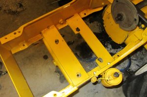
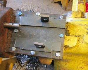
With the driveline and clutch installed, the next problem was the shift mechanism. Since the driveshaft extended right through where the gearshift used to be, it was necessary to install a completely new, different shifting mechanism. I took a ¼” by 1” flat and formed a connection that fit into the top of the shifter fork and bolted it in place. I mounted one of these on each side of the driveshaft. I mounted a piece of ¼” plate with two slots in it to cover the transmission opening.

I had planned to use accordion boots to cover the slots for the shift mechanism, but there just wasn’t enough room. After a lot of thought and discussion with some friends, I decided I’d cover the slots with two “sliding” plates. I also went with a heavier (90 wt.) transmission fluid to limit oil loss.
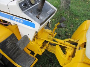
With that, the hard part of the project was done. I considered making some sort of mechanism so I’d only have one gearshift lever, but that got really complicated. I decided instead to go with two levers. It took some time, but I got the clutch pedal and gearshift levers installed.

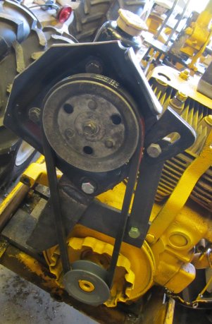
The only problem remaining was the steering. I wanted hydraulic steering like Artie I. I still had a power steering pump from a 1986 Honda Civic that I had purchased for Artie I but never used. I had read on the web that this pump could be used with a counterclockwise rotation. I set up a test stand with a reversible drill to try it out.

I found out the pump required a clockwise rotation. Don’t believe everything you read on the web!!! But when I took the pump apart I found out that everything on the inside was symmetrical. So, I just moved the drive shaft and gear from the left side to the right side, and I had a counterclockwise rotating pump.
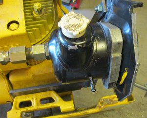
I mounted the pump to a plate bolted to the engine block behind the starter/generator bracket.
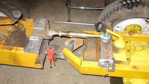
I used the same steering “setup” that I’d used in Artie I.
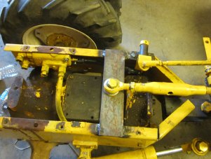
(In the picture I’d found a wideframe rear end and replaced the temporary frame that I’d been using.)
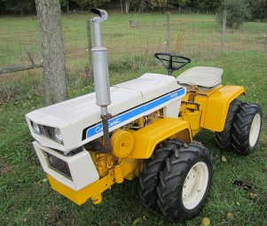
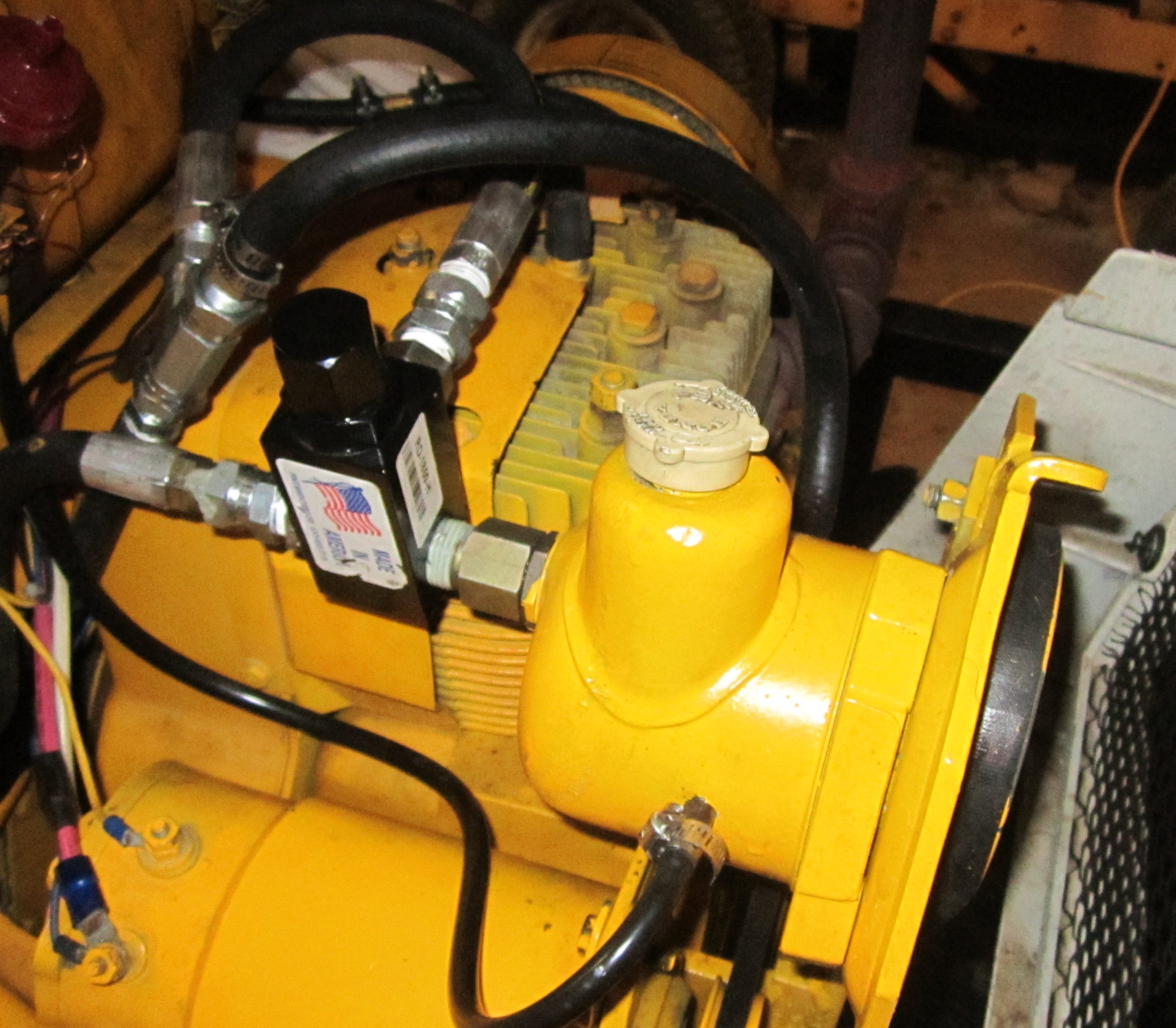
And, that was it. All the sheet metal from Artie I fit on the new “Artie” and I was ready to paint and try it out. The only problem I encountered was with a leaking seal on the front of the power steering pump. A little investigation determined that the pressure was getting too high when the steering “bottomed out” the hydraulic cylinder used for steering. I couldn’t find a pressure relief valve in the range I wanted, so I purchased a higher pressure relief valve and replaced the spring with a weaker one. It worked great on the first try. Again, it’s better to be lucky than good.
I was really pleased with the final result. I have a much smoother, consistent motion as well as smoother steering. I like a gear drive Cub Cadet!!!