This is an article that I wrote for Cadet Connection. It was published in the Fall and Winter issues in 2015. It’s a great magazine for any Cub Cadet collector and I highly recommend it.
I wanted to build a Cub Cadet Dozer for several years. I had started on one a few years ago and had made significant progress on it. I have had some experience with smaller dozers and know that you don’t want a lot of speed. With that in mind, I worked on a design that would really slow down the ground speed. I also had learned from experience that I wanted something with an overall length and width comparable to a standard Cub Cadet for hauling purposes. I had gotten far enough along to shorten a Cub Cadet’s axles, start the construction of a frame and create a reduction drive as well as an increased drive speed for a braking system.
 I wasn’t particularly happy with the way the project was going. As a result, I disassembled and quit on it when I got an opportunity to purchase our GroundSaw and Danuser post hole digger.
Two things got me interested in the project again. First, I had installed a creeper drive in my Cub Cadet with a front end loader. I had been advised by several people that a creeper would not hold up under these circumstances. But I had used the loader hard for two years with no signs of failure or reduction in performance. It would be a lot easier to use a creeper to reduce the speed than what I’d tried before.
Secondly, I got to see and drive a Cub Cadet dozer at the 2012 Lawn and Garden Tractor Extravaganza in Evansville, Indiana. The dozer was owned by Sherrill Toone. It had no speed reduction and was about the right speed – at least for display. And, by mounting a sprocket directly to the rear axle, the width turned out to be just about right without having to shorten the axles.

While there were a lot of things that I wanted to do differently, I really liked Sherrill’s basic design. Also, I had decided that if the ground speed was too fast, I could always add a creeper.
One of the factors that had stopped me on my original design was the cost of the chain and sprockets for the track. Fortunately, about the time I had decided that I again wanted to start a dozer project; I found some 2060HKII roller chain at a good price that would work nicely.

As an added bonus, this 2060 chain has the tabs that I needed to attach the pads to the track. The chain was a little smaller than I had originally planned to use, but I had gained a lot of confidence in 2060 chain from my experience with the GroundSaw. Sprockets for the 2060 chain were also a whole lot cheaper than what I’d been looking at previously. I purchased 40 feet of chain so that I could have 4 ten foot sections to use on my dozer project.
A lot of mini-dozers I’ve seen use just one chain for each track. I didn’t really like that design and decided I’d use two chains for each track. After a lot of time thinking, planning, measuring, and calculating, I ordered eight 60 pitch 54 tooth sprockets with 4 X-hubs with a 1 1/4 inch bore. Each of the four front sprockets would get one of the hubs. Two hubs mated together would make the spacing I wanted between the two chains for the front. I ordered 1 ¼ O.D. by 1 inch I.D. flanged, sleeve bearings to fit each of the hubs so the front sprockets could be mounted on 1 inch diameter shafts. Each set of rear sprockets would be press mounted and welded on a 2 inch O.D. thick wall tube and would bolt directly to the rear axle of the Cub Cadet.
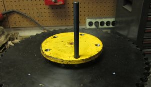
The first order of business was to determine if the spacing provided by the X-hubs agreed with the published value. I placed the sleeve bearings in the hub, mounted them on a 1 inch diameter shaft to keep them aligned and welded them together. I also added a grease fitting.

To my disappointment, when I placed the sprockets on the hubs and placed the hubs on a one inch shaft, everything didn’t line up like it should. Apparently the hubs weren’t as precision as I’d assumed they would be. After some more thought (I spend a lot of time just thinking and figuring on these projects), I came up with a plan. Since I had to have mounting holes in the rear sprockets anyway, I decided I’d drill mounting holes in all the sprockets and use through bolts to adjust the alignment before welding.
At least I had planned ahead and used a hub to properly locate the holes for mounting the rear sprockets before I welded them together. I had placed one of the hubs in my vice with a bearing installed for a one inch diameter shaft.

By placing a sprocket over the hub and sliding a rear axle down through the bearing, I could use a transfer punch to easily determine the location of the holes I needed to drill.
With one set of holes drilled, I could match up the rest of the sprockets and drill mounting holes in them as well. I also had to make sure the teeth on my pattern lined up on each of the sprockets before drilling. With the holes drilled, I clamped a length of 1 inch diameter shaft in my vice and used a dial indicator to adjust the mounted sprocket for proper alignment.


By tightening and loosening the connecting bolts, I got the inner sprocket in alignment and welded it in place. With the inner sprocket held in place, it was a simple matter (took some time) to align the outer sprocket and weld it in position.
With the front sprockets completed, I knew the spacing that was required on the rear sprockets. I had a press fit between the rear sprocket and the piece of thick wall tubing that I had so I pressed one sprocket on, checked for square and welded it in place. I then used coupler nuts to make four proper length spacers to go between the sprockets.

In the picture you’ll notice cardboard spacers between the bolt and coupler nut. The length of the coupler nut required the bolt be screwed in so far there wasn’t a space for a washer or double nut. By tightening the bolt until it smashed the cardboard, I got a tight fit that held the proper length. It took a little work, but I got the spacers installed between the sprockets and everything lined up. The mounting bolts placed through both sprockets held everything in place.

With everything square and in the correct position, I welded both sprockets in their final position and mounted them on the rear axle. One thing quickly became obvious. If the sprockets were mounted flush against the rear Cub Cadet axle, there wouldn’t be enough room for my foot between the track and frame of the Cub Cadet. I measured the width of my shoe and determined I needed a 1 inch spacer for each rear axle. It turned out that a 7 ½ pound barbell weight was exactly what I needed to get the additional 1 inch spacing.

With the spacer in position, I mounted the rear sprockets.

With the rear sprocket in place, I mounted the roller chain so I could determine the location of the front sprocket.

You can see in the picture that I used a board to keep the sprocket from rolling backwards. With the chain in the “slack” position, I determined where I could place a cross member to hold the front sprockets in place. There was already one hole in the Cub Cadet frame that could be used to hold the cross member in place. Ordinarily, I don’t like to modify any part of a Cub Cadet that I’m using on these projects. However, the frame that I’d chosen for this project had been so modified by a previous owner that a few more holes weren’t going to make any difference. I measured the distance outside to outside of the rear sprockets and determined the distance to be a little less than 32 inches. I had to allow for clearance for the bearing flanges for the front end, and I wanted to add a washer as a spacer on each side of the sprockets. That meant that the 2” by 2” cross member would have to be 32 3/8 inches long. The front axles had to be located in slots so that I could have spring tension on each axle. I cut 5 inch long, 1 inch wide slots in four sections of 3/8” by 3” flat.

The top two top pieces in the picture are made to fit over the 2” by 2” tubing and bolt to the frame of the Cub Cadet. The two 13 inch long pieces in the center will “box in” the end of the 2” by 2” tubing, and the two 10.75 inch long pieces at the bottom of the picture butt up against the tubing.

It required a 3 ¾” spacing between the two supports to allow sufficient room for the bearing flanges and washer spacers. I clamped and welded the inside supports in place.

The outside bracket needed a channel structure to mount the axle spring, and I wanted a channel section on the inside for the added strength. So I welded a 3 inch wide piece of ¼” flat across the top of each bracket. The flat across the top on the inside bracket in the picture below was eventually bent down and welded to the tubing.

With everything welded, I could mount the front carriage and attach the front sprockets.

I found some springs at a local farm supply that worked to provide the proper spring tension to the chain.

All that was left was to add steering, and I’d be able to drive the dozer!!!
I’d been thinking about the steering since starting the project. It looked like the creeper slot in the frame was at just the right position for the left steering lever. (Hope I won’t need a creeper!!!) And, there was a hole in the frame of the Cub Cadet that looked to be just in the right location for a pivot for the lever. I measured across the frame and using my trusty angle grinder and cutoff wheel, cut out a symmetrical slot for the second steering lever.

Since I’d already destroyed the original integrity of the frame, I decided I’d weld the pivot mountings in place. I usually prefer bolting over welding, but this looked like a good place to weld. I drilled out the existing hole in the frame to accept a 1” O.D. by ¾” I.D. piece of tubing. I drilled a 1” diameter hole in a section of ¼” by 2” flat to hold the inner end of the tubing and welded everything in place.


I slid a ¾” diameter piece of cold rolled through the tubing. If I welded brackets to both ends of the ¾” piece, it would be impossible to disassemble in the future. So I decided I’d weld the outer section and use a roll pin or bolt to hold the lever bracket on the inside end.


I bolted the steering levers to the inner bracket. That allows me to unbolt the lever, remove the inner bracket and slide the ¾” piece out of the tube for lubrication, replacement or modification.


It was a relatively simple matter to install a linkage from the outer bracket to the rear disk brake on each side. And, the dozer was ready to drive!!! The first time I drove it I only moved it about 3 feet backwards and 3 feet forward. But everything, including the steering, seemed to work fine. Unfortunately, the part of the project I always enjoy and find challenging was completed and the stuff I don’t care for remained. I needed to add all the sheet metal work and try to make it look presentable. It also needed bogie wheels but that would have to wait until I found something I liked.
Adding fenders turned out to be quite a challenge because of the limitations I’d placed on the overall width. It was going to be difficult to get enough room between the track and Cub Cadet frame to make room for my feet.
I began by making a mock up of two different possibilities. I had a couple of old fenders that were rusted beyond repair that I cut up and added to each side. On the left side I just cut out a notch in the Cub Cadet fender so I could mount the “dozer” fender. On the right side, I cut away the entire Cub Cadet fender leaving only the mounting section and used only the “dozer” fender. You can see my helper in the pictures.

In the picture you can see the original Cub Cadet fender along with the added dozer fender. I’d left the dozer fender long enough that I could adjust the length later. The dozer fender is just laying on wooden spacers laid on top of the dozer track chain.

I was crowded for shop space on the right side of the tractor so it was difficult to get a really good picture. But you can see the dozer fender lying against only the inner section of the Cub Cadet fender. I sent both pictures to several relatives and friends and asked for an opinion. Universally they all replied that the left side had more of the characteristics of a Cub Cadet and the right side looked more like a dozer. After a couple days of thinking about it, I decided I’d go with the left side look.
I had two fenders from a 122 Cub Cadet that were in good shape so I cut out the necessary notch. I added a section of 2” by 2” angle on the inside of the Cub Cadet fender at the correct height for the dozer fender to rest on when mounted. I welded a section of 3/8” by 2 ½ inch flat that extended out from the 2 X 2 angle to support the outer edge of the dozer fender.

The 1/8” by ½” strip in the picture is a spacer to make up for the 1/8” thickness of the 2” by 2” angle that the dozer fender rests on.
I welded together a mounting bracket and bolted it to the front carriage to support the front of the dozer fender.


I shortened the fenders, welded pieces of ¾” by ¾” angle to the bottom for added strength and bolted the dozer fenders in place.


While working on the fenders, I’d been thinking about how to mount the bogie wheels. The foot rests on a Cub Cadet are given extra support by a cross member that ordinarily serves a dual purpose as a manual lift. I’d replaced this lift by a ¾” diameter shaft. The shaft was originally held in position by a triangular shaped section on each side. I replaced this section with a rectangular section that extended down far enough to support a 1 inch diameter shaft below the ¾” diameter shaft. I drilled a 1 inch diameter hole in an 11 inch long section of 2” by 2” tubing that I bolted to the front carriage. The picture was taken after the bogie wheels were mounted and the “skirt” mounting brackets were in place.

I had found some cheap wheels that I felt would work well as bogie wheels. They had a rated load of 500 pounds each.

I cut and drilled brackets and axles for each of the wheels.


The two longer brackets support a lower bogie wheel as well as an upper wheel to support the weight of the track. I c-clamped and tack welded the brackets in place. I used the tack welds to hold the brackets in position so I could remove the c-clamps for drilling mounting holes.


After the holes were drilled I added bolts and placed the mounting bracket and wheels back on the dozer.

I left the tack welds but knew I could grind them off if I needed to remove the mounting brackets.
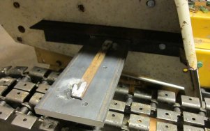
Now all that was left to do was mount the pads to the tracks – all 160 of them. I had planned to saw all the pads to the correct length, but a good friend had a neighbor that volunteered to shear them all to length. The pads were made from 3/16” by 1 ¼” flat cut to a length of 6 ½”. After they were cut to length each pad had to have four holes drilled to mount to the roller chain. I had thought about welding the pads to the chain knowing that would be a lot faster, but I liked the idea of being able to easily replace or modify a pad if it became necessary.
After getting the pads sheared to the correct length, I made a fixture to hold the pads for drilling the four mounting holes. I drilled 5 pads at a time.

The top pad is a pattern that I used over and over and the bottom 4 pads are just spacers in the fixture. I originally made 4 patterns so that I could switch them out if necessary.
I would drill 20 pads (5 at a time) and them mount them to make sure my pattern hadn’t worn to the point the holes were not in the correct position. It took a while, but I got all 160 pads drilled and mounted.

After mounting the pads, I reassembled everything and tried it out. The dozer didn’t turn as well as I wanted so I extended the outer linkage to get more “throw”. That seemed to cure the problem.

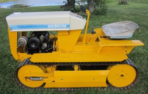
It was winter so I put the dozer in storage to wait for warmer weather to paint. With warmer weather I got everything painted in time for a July show. There’s a video of the Mini Dozer in the Video section of this website.


If you have any questions or comments you can contact me through this website.
