All posts by jfunk

Danuser CD-1 Post Hold Digger

This is a video taken while testing out our Danuser CD-1 Post Hole Digger.  This was the first hole I dug with it so I was still getting used to the controls.  We had an extreme drought the summer this video was taken so the ground was really hard.  The post hole digger did a nice job.


Last Modified On: 2014-03-15 13:03:24

Hawk-Bilt Groundsaw

This is a video taken while testing out our Model 1200 Hawk Bilt GroundSaw.  It really moves along at a pretty good speed.  I didn’t use enough down-pressure, so it’s not really deep, but it works great!


Last Modified On: 2014-03-15 13:03:48

Haban Sickle Bar Mower

We use our Haban Sickle bar mower to mow around our lake.  Later in the summer the water level gets lower, the ground isn’t as soft, and the 4 foot bar will reach all the way to the water’s edge.


I wanted to show a close-up of the guards and knifes.  (I’m rotating the pulley by hand and the tractor engine is shut off in the video.)  The Haban has a different guard than mowers I grew up using.  All other guards I’ve seen extend below and above the knife.  The Haban actually does a better job of not clogging with the shorter, simplier guards.


Last Modified On: 2014-03-15 13:04:18

E-Z Vac Mowing Attachment

We hadn’t used our E-Z Vac attachment for a couple of years, but with the wet spring this year the grass was really growing fast.  We don’t bag our grass clippings so with the wet spring, the mower was having to deal with a lot of dead grass clippings.  The E-Z Vac does a great job.  In the later part of the video you can see that it really packs the grass in the trailer.


Last Modified On: 2014-03-15 13:06:05

Groundsaws / Trenchers

Operation Manual for a Hawk Bilt Model 1200 “Groundsaw” Trencher for IHC Cub Cadet models 100, 102, 122

Installation Manual for a Hawk Bilt Model 1200 “Groundsaw” Trencher for IHC Cub Cadet models 100, 102, 122 (Thanks to Scott Bleich for providing a copy of these instructions.  I’m sure that everyone that uses them will appreciate his contribution.)

Vermeer M-147 A Trencher owner’s manual.

Operation and parts manual for stand-alone Hawk Bilt Model 750 Groundsaw (Thanks to the Inhofer family for providing a copy of this manual.  I appreciate their contribution.)


Last Modified On: 2021-02-21 15:49:09

Z Bender

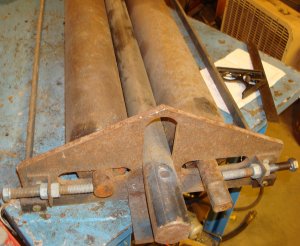
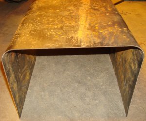
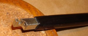
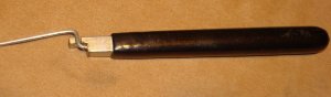
I used to use a couple needle nose pliers to make the z bends for throttle and choke cables.  Eventually, I purchased a device made specifically for that task.  While it doesn’t make as compact a bend as I like, I generally use it if I don’t want to take the time to remove the cables from the Cub Cadet.  I’d thought I’d include a description here since it’s a process that’s pretty simple to duplicate.  The bender looks like this:

z-bender-1
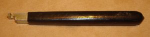
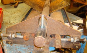
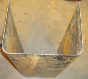
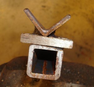
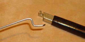
Since it’s not obvious from the picture, here’s two closeups of the ends.

z-bender-3-end view 2z-bender-2-end view


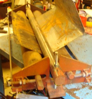
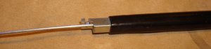
To use the bender, insert the throttle wire in the hole in the end.

z-bender-4-with wire
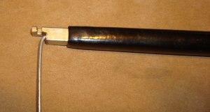
After the wire is inserted in the hole, it is bent forward (or downward depending on your perspective).

z-bender-5-first bend
After the bend, the wire is rotated around until it is seated in the slot in the tool.

z-bender-6-first bend rotate
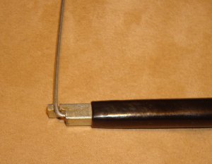
The wire is then bent forward.

z-bender-7-second bend
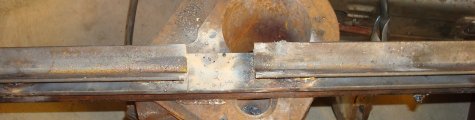
The wire can then be rotated out of the slot and removed from the bender.  The finished product looks like:

z-bender-8-finished product
Notice in the above photo that the resulted z bend is not very compact and the bends are more rounded then I like.  The device is easy to use and it’s pretty fail safe, but although it’s not obvious in the picture, it’s a fairly “wide” z bend.

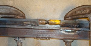
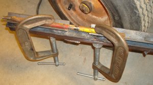
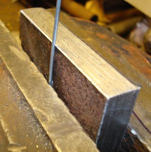
If I have the cable removed from the tractor, I came up with another method that I prefer.  I made a fixture by drilling a through hole (5/64″) in the side of a  1/2″ piece of steel from the scrap pile.  Begin by placing the wire in a vice.  The wire should be about a 1/4″ into the vice.

z-bender-9-wire in vice
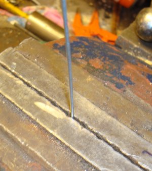
Using a hammer, make a bend.  The hammer assures a sharp 90 degree bend.

z-bender-10-first bend in vice
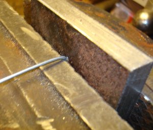
Remove the wire from the vice and stick the 1/4″ length in the fixture.

z-bender-11-wire in fixture
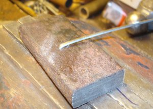
Place the wire and fixture in the vice.  The depth that you place it will determine the width of the z-bend.

z-bender-12-fixture in vice
Again, using a hammer bend the wire forward.

z-bender-13-second bend in vie
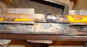
Remove the wire and fixture from the vice and you have a z-bend.

z-bender-14-finished product and fixture
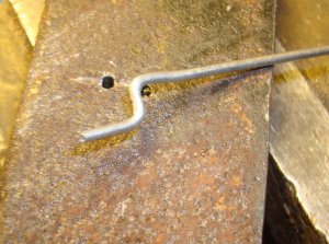
It’s not obvious from the picture, but the z-bend created has much sharper corners and is much narrower.

Again, I hope you find this article useful.  I’m sure with a little creativity someone could come up with an even better and simpler bender.  If you do, drop me an email.  I’d be glad to hear from you.

Last Modified On: 2014-03-15 11:27:46

Roll Bender

When I first started making the Mini-560, I needed a way to make the hood.  I had two sophmore students that were looking for a project to work on.  I gave them a project of making a bender that would produce a 2″ diameter 90 degree bend.  They came up with the bender discussed here.  If you’re a little older and grew up on a farm, you may recognize the two outer rows as coming from an Allis Chalmers baler.

roll-bender-2-bende rright endroll-bender-1-bender left end


I’ve used this roll bender to make the hood for the Mini-560, Mini-H and Artie and I’m currently using it to make a hood for a Mini-Cub I’m working on.  It’s not real fast and takes a lot of patience but I’ve been very satisfied with the results.

As mentioned the two outer rollers are from an Allis Chalmers baler.  The center bar is a piece of 2″ hot rolled steel.  (I also have a 1″ O.D. pipe that I can use to make a smaller bend radius.)  The two outer rolls are adjustable in and out to allow for clearance for different thickness materials and different radius bends.  The hoods for the Mini-H, Mini-560 and Artie were all made of 16 gage material.  18 gage material is a lot easier to bend but obviously isn’t as dent resistant as the 16 gage material.  A piece of 1/2″ all thread on each end is used to “pull” the 2″ diameter bar down between the outer rolls and bend the metal.

roll-bender-3-left end view
The pictures used to illustrate how the bender works are for a Mini-Cub that I’m currently working on.

roll-bender-5-right end partial bendroll-bender-4-leftt end partial bend


As can be seen in the pictures, one bend has been completed and the other bend is in progress.  It requires some calculation and experimentation to determine where the bend should be placed to get the proper width hood.  While the placement of sheet metal to obtain the required width can be calculated, the amount of “depth” for the 2″ bar to create a 90 degree bend has to be determined by experimentation.  I always practice on a couple pieces of scrap sheet metal to determine where to place the sheet metal and how much to screw down the all thread.

The finished hood looks like:

roll-bender-7-finished hood 4roll-bender-6-finished hood 3


The metal I used has a little surface rust.  I waited until a day when there was no rain to order it, but the supplier must have loaded it the day before in the rain.  It’s only surface rust and won’t hurt anything.  Also, the hood is too tall and the sides need to be shorter.  I’ll find someone with a shear to do that for me.  I’ll make the “gas tank part” of the hood before determining that height.

As usual, if you have any comments or suggestions for  improvement, just drop me an email.  I’m always open to better ways of doing things.

Last Modified On: 2014-03-15 11:26:57

Centering a Cross Hole in a Shaft

Shaft Centers

If you repair Cub Cadets or “manufacture” custom Cub Cadets there’s a lot of occasions when you need to drill a centered hole through a shaft. If you can accurately create a hole centered in a shaft, you can manufacture your own drive shafts as well as make some custom clutch shafts, steering shafts, etc. The method described requires only a drill press, a v-block, a long center drill and sharp bits. The v-block pictured in the following discussion was purchased from Harbor Freight. I generally don’t recommend purchasing any discount power tools from Harbor Freight, but there are certain tools that work OK. The long center drill and bits (I use cobalt drills for this) were purchased from a local tool supply shop. A shorter center drill could be used along with some precision ¼” rod.

center-cross-1-centering quill


Begin by assuring the table on your drill press is perpendicular with the direction of quill travel. Machinist probably have a more precision way of doing this, but I use a combination square and the long center drill. The long center drill could be replaced with a section of ¼” rod. Once the table is squared with the quill travel it should be occasionally checked to make sure it remains perpendicular. This is especially important if you have to loosen and relocate the drill table.


Make sure you check square at two positions at right angles to the rod. If at all possible, position the table where there’s enough distance between the drill chuck and table that you can drill a hole in the shaft without repositioning the table. Once your drill press is “squared” and the table secured in position, the v-block needs to be properly located. I do this using a drive shaft that’s been removed from a narrow frame Cub Cadet. Place the shaft in the v-block and move the v-block around until the center drill or ¼” rod slides freely in and out of the hole in the shaft. The drive shaft works well for this as it contains factory centered ¼” holes.
Once the v-block is located so that the center drill or rod slides easily in and out of the hole in the shaft, c-clamp the v-block in position. It requires a little coordination to hold the shaft in the v-block while keeping everything aligned, but I’ve done it several times, and you get better with practice. I didn’t take a picture of just the v-block c-clamped in position, but I use 3 small c-clamps to hold it securely.

center-cross-2-center_5

With the v-block in the correct position, c-clamp the new shaft in position. Use the center drill to start the new hole. This is where I find the long center drill to be very useful. It is close enough to the length of most drill bits that I don’t have to worry about the distance between the chuck and shaft.  Once I get it established for the center drill, it also works for the length of a standard bit.

center-cross-4-center_3center-cross-3-center_4


With the hole started with the center drill, replace the center drill with a standard bit to finish the job. I always use cobalt bits for this, but just make sure you have properly sharpened bits so they don’t “wander” off center.

center-cross-6-center1center-cross-5-center_2


That’s the process. The only problem that I’ve encountered is when I didn’t properly square the quill travel with the drill press table. If it’s a really critical job, I always experiment with a scrap piece of material first. The only problem I’ve had with the v-block is that it won’t hold anything smaller then a 5/8” shaft. Since most of the shafting on a narrow frame Cub Cadet is 5/8” or larger, that generally hasn’t been a problem.

Last Modified On: 2014-03-15 11:23:21

Shortening or Lengthening a Shaft

I’ve had several occasions to lengthen or shorten shafts on some of the custom Cub Cadet stuff I’ve done. The mini-Cub I’m currently working on required extending the steering shaft, tie rods and right rear axle. I used to just c-clamp two sections in a piece of angle and weld them together. But it’s very difficult to clamp a round section in a piece of angle. The c-clamp tends to slide off to one side. The picture is a fixture that I made to permit c-clamping two round sections together for welding.

shaft-2-fixture endshaft-1-shaft_6


The fixture consists of a length of 1” angle welded to a section of ¼” X 1” flat. I welded a continuous length of angle to the flat and then cut out the section shown. By making the cut after welding, I was sure everything was properly lined up. After welding the angle to the flat section it became obvious that the flat did not have the rigidity necessary to prevent a welded shaft from deflecting as it cooled. So I reinforced it with a heavy section of 1” square tubing. (It was just a scrap piece of tubing that I found in the scrap pile. That’s why you may notice a piece of weld on it that serves no purpose.) The 1” square tubing on the bottom gives a nice flat surface for one half of the c-clamp.

With the fixture made, c-clamp the two sections to be welded together in the fixture.

shaft-4-shaft_3shaft-3-shaft_1


Notice that the ends of each shaft section have been beveled for better weld penetration. You can also see that piece of weld on the square tubing that I mentioned earlier. Some day I’ll grind that off!!!
With the shaft secured in position, it’s ready to be welded.

shaft-5-shaft_4
Once the shaft has been welded allow it to completely cool before removing it or rotating it to do additional welding.  Generally the angle is “thick” enough that you won’t have to grind the weld until you’re completely finished.  However, if the weld interferes and doesn’t allow the shaft to seat properly in the angle when it’s rotated, it will have to be ground off.

This is one of those things that seem really simple when you see how it’s done.  But it’s a process I’ve developed over several years of trial and error.  If you have a simplier or better method, I’d be glad to hear from you.  Just drop me an email.

Last Modified On: 2014-03-15 11:24:27